System and apparatus for testing and/or evaluating an industrial catalyst

a technology for industrial catalysts and systems, applied in chemical instruments and processes, chemical analysis using catalysts, chemical/physical processes, etc., can solve the problems of long time period, high cost, and difficult catalyst design, and achieve the effect of reducing the amount of time needed and reducing the cos

Active Publication Date: 2022-05-31
SAUDI ARABIAN OIL CO
View PDF39 Cites 0 Cited by
  • Summary
  • Abstract
  • Description
  • Claims
  • Application Information

AI Technical Summary

Benefits of technology

[0016]The invention is an apparatus and method for assessing catalysts. The invention affords the artisan the opportunity to test the catalyst under completely real time conditions. A test unit which can assess a catalyst in operation on a mixture of hydrocarbon feedstock and a gas, e.g., hydrogen, which can be pure hydrogen, or mixes of hydrogen and other gases, depending upon the testing protocol under consideration, is installed adjacent to a commercial reactor system, and receives a sample of the mixture of hydrocarbon feedstock and gas, e.g., hydrogen, which is identical to one used in the commercial reactor, under the identical conditions of the reaction. While the invention might be viewed as a “mini pilot plant,” this is not completely accurate, as a pilot plant can approximate, but cannot duplicate, the conditions of a commercial reactor system. The invention permits vast reductions in the amount of time necessary to assess a catalyst resulting in, e.g., vast reductions in the cost of this aspect of the petroleum refining industry.

Problems solved by technology

The design of catalysts is challenging, and when one is interested in a specific reaction or specific reactions, multiple options are presented.
These testing procedures are expensive and require a great deal of time.
Testing stability of a catalyst requires a longer period of time than the other properties being evaluated and, given limited resources, “bottlenecks” the ability to evaluate further catalysts.
The methods available for overcoming this bottleneck are not satisfactory.
For example, building additional pilot plants is very expensive.
This approach means that one cannot assess the catalyst until after the cycle is completed.
Both approaches are lengthy, and expensive.
The configuration of the test system does not allow for testing of gas phase components, i.e., hydrogen containing gas components.
Notwithstanding the teachings of the '798 patent, the art lacks a methodology for testing catalysts with all of (i) liquid only feedstocks, (ii) gas only feedstocks, and (iii) mixed feedstocks of both liquids and gases.

Method used


Image

  • System and apparatus for testing and/or evaluating an industrial catalyst
  • System and apparatus for testing and/or evaluating an industrial catalyst
  • System and apparatus for testing and/or evaluating an industrial catalyst

Examples


Embodiment Construction

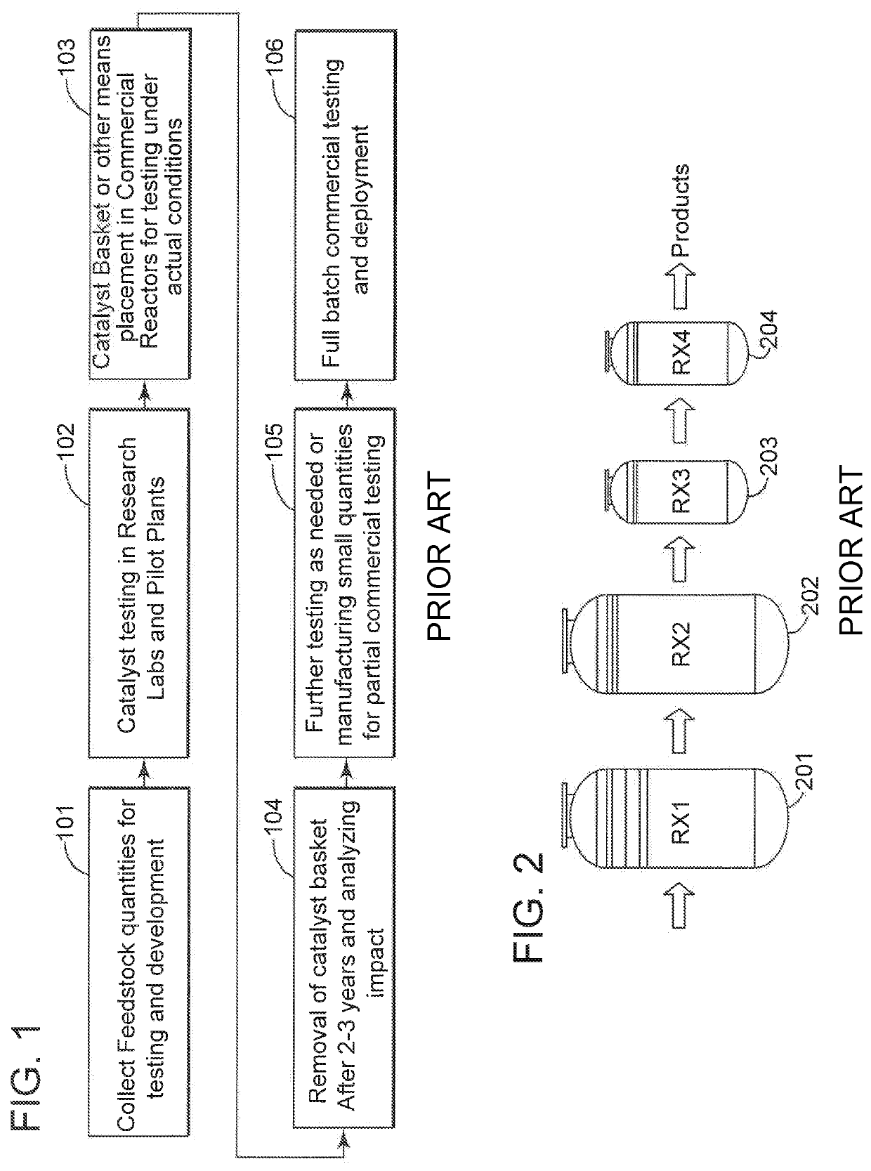
[0030]Referring to the drawings, FIG. 1 in particular, one can use the standard, prior art process for evaluating a catalyst of interest. Sample of feedstock are collected “101”, and then tested in a research lab and / or pilot plant “102”, as described supra. Any catalysts which show promise are then returned for “basket placement” or “basket testing”“103”, in commercial reactors, also as described supra. As noted, again supra, this can take as long as 2-3 years “104”, and may be followed by further testing “105” and “106”.

[0031]An alternative prior art process, also discussed supra, is shown in FIG. 2.

[0032]FIG. 2 shows the type of system described in, e.g., U.S. Pat. No. 8,361,798, cited supra. This is a two phase system. A commercial reactor “201” is connected to a test reactor “202” via a liquid transport means, which is not shown. Only liquid moves to test reactor “202”, which contains the catalyst of interest. Products of the test reactor “202” move to further chambers “203” an...


PUM

PropertyMeasurementUnit
lengthsaaaaaaaaaa
lengthsaaaaaaaaaa
internal diameteraaaaaaaaaa

Abstract

The invention relates to an integrated process for assessing one or more properties of a catalyst. In the method, a standard chemical reactor or reactors is / are provided, and a bypass means is also provided, to transport a sample of whatever is added to the industrial reactor, to the test reactor. Both gases and liquids are transferred to the test reactor.

Description

FIELD OF THE INVENTION[0001]The invention relates to an apparatus for useful in testing properties of a catalyst, as well as processes for using this apparatus for testing a catalyst.BACKGROUND AND PRIOR ART[0002]Process conversion plants used in industries such as oil, gas, chemical, and petrochemicals rely on catalysts as essential components of processes designed to yield the maximum amount of a desired product or products while simultaneously optimizing the energy requirements necessary to achieve these aims.[0003]“Catalysts” as used in these fields, generally comprise a catalytically active metal, such as one or more of Co, Mo, Ni, and W (these are exemplary and not limitative), and a support material, which may be but is not necessarily, one of a crystalline zeolite, such as an amorphous alumina, titania, or silica. (It is to be understood that by “active metal,” this application means one or more than one, combined, and this is also the case for the components of the support)...

Claims


Application Information

Patent Timeline
Patent Type & Authority Patents(United States)
IPC IPC(8): G01N31/10
CPCG01N31/10B01J19/0046B01J8/0457B01J2219/00015B01J2219/00279B01J2219/00299B01J2219/00747B01J8/001B01J2208/00035B01J2208/00654B01J2208/00805B01J2208/024
Inventor ALKHANI, ANAS FARKADKOSEOGLU, OMER REFA
Owner SAUDI ARABIAN OIL CO
Why Eureka
Try Eureka