Signal processing apparatus and signal processing method

a signal processing and signal processing technology, applied in image enhancement, image analysis, instruments, etc., can solve the problems of windshield distortion and lens distortion, and achieve the effect of easy estimation of image distortion

Active Publication Date: 2022-05-31
SONY CORP
View PDF20 Cites 0 Cited by
  • Summary
  • Abstract
  • Description
  • Claims
  • Application Information

AI Technical Summary

Benefits of technology

[0014]An aspect of the present technology makes it possible to easily estimate image distortion occurring in a case where an image is captured through a transmissive body that allows light to pass through.
[0015]It should be noted that the present technology is not necessarily limited to the above advantages. The present technology may provide any other advantages described in the present disclosure.

Problems solved by technology

Further, in a case, for example, where a camera disposed in a compartment of a vehicle captures an image of a forward view from the vehicle through a windshield (front window), windshield distortion occurs in addition to the lens distortion.

Method used


Image

  • Signal processing apparatus and signal processing method
  • Signal processing apparatus and signal processing method
  • Signal processing apparatus and signal processing method

Examples


first embodiment

1. First Embodiment

[0048]A first embodiment of the present technology will now be described with reference to FIGS. 1 to 10.

11>

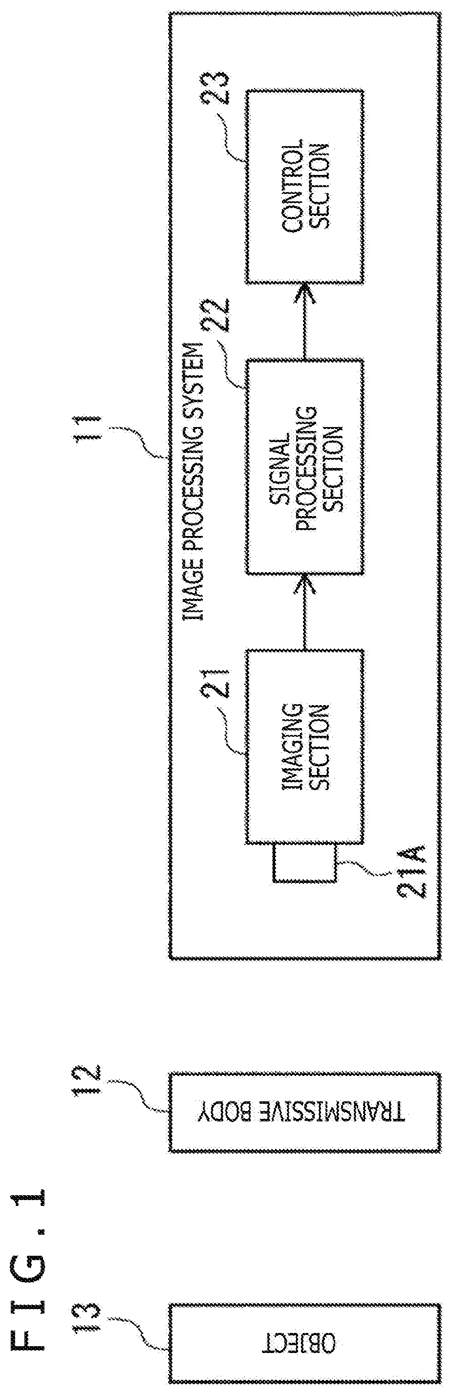
[0049]FIG. 1 illustrates an example configuration of an image processing system 11 according to a first embodiment of the present technology.

[0050]The image processing system 11 captures an image of an object 13 through a transmissive body 12 disposed between the object 13 and the image processing system 11, and performs various processes by using the obtained image (hereinafter referred to as the captured image).

[0051]The transmissive body 12 is a transparent or translucent body that allows light to pass through, and includes, for example, a visor of a wearable device for AR (Augmented Reality) or VR (Virtual Reality) or a windshield of a vehicle. Light from the object 13 is transmitted through the transmissive body 12 and incident on a lens 21A of an imaging section 21.

[0052]It should be noted that the transmissive body 12 may be included in the image proc...

second embodiment

2. Second Embodiment

[0144]A second embodiment of the present technology will now be described with reference to FIGS. 11 to 14.

[0145]As compared with the first embodiment, the second embodiment reduces the amount of computation required for the distortion correction process, and thus increases the speed of processing.

201>

[0146]FIG. 11 illustrates an example configuration of an image processing system 201 according to the second embodiment of the present technology. It should be noted that elements depicted in FIG. 11 and corresponding to those in the image processing system 11 depicted in FIG. 1 are designated by the same reference symbols as the corresponding elements in FIG. 1, and in some cases will not be redundantly described.

[0147]The image processing system 201 differs from the image processing system 11 in that the former includes a signal processing section 211 instead of the signal processing section 22.

211>

[0148]FIG. 12 illustrates an example configuration of the signal p...

third embodiment

3. Third Embodiment

[0172]A third embodiment of the present technology will now be described with reference to FIGS. 15 to 18.

[0173]The first and second embodiments have been described in relation to processing that is performed in a case where the internal parameter (internal matrix K in Equation (1)) and external parameters (rotation component R in Equation (2) and translation component t in Equation (3)) of the imaging section 21 are known. Meanwhile, the third embodiment will be described in relation to processing that is performed in a case where the internal matrix K, the rotation component R, and the translation component t are unknown.

301>

[0174]FIG. 15 illustrate an example configuration of an image processing system 301 according to the third embodiment of the present technology. It should be noted that elements depicted in FIG. 15 and corresponding to those in the image processing system 201 depicted in FIG. 11 are designated by the same reference numerals as the correspond...


PUM


Abstract

Provided is a signal processing apparatus that estimates image distortion in a case where images are captured through a transmissive body allowing light to pass through. The signal processing apparatus includes a lens distortion estimation section that estimates lens distortion based on a location of a feature point in a first image and a second image of an object. The first image is captured by an imaging section through a transmissive body and a lens that allow light to pass through. The second image is free of transmissive body distortion caused by the transmissive body and free of the lens distortion caused by the lens. The apparatus further includes a transmissive body distortion estimation section that estimates the transmissive body distortion based on the location of the feature point in the first image and a third image that is obtained by removing the estimated lens distortion from the first image.

Description

CROSS REFERENCE TO RELATED APPLICATIONS[0001]This application is a U.S. National Phase of International Patent Application No. PCT / JP2019 / 006775 filed on Feb. 22, 2019, which claims priority benefit of Japanese Patent Application No. JP 2018-041471 filed in the Japan Patent Office on Mar. 8, 2018. Each of the above-referenced applications is hereby incorporated herein by reference in its entirety.TECHNICAL FIELD[0002]The present technology relates to a signal processing apparatus, a signal processing method, and a program, and more particularly to a signal processing apparatus, a signal processing method, and a program that are suitable for a case where images are captured through a transmissive body allowing light to pass through.BACKGROUND ART[0003]In the past, a technology for correcting lens distortion caused by a lens of a camera has been proposed (refer, for example, to PTL 1).[0004]Further, in a case, for example, where a camera disposed in a compartment of a vehicle captures...

Claims


Application Information

Patent Timeline
Patent Type & Authority Patents(United States)
IPC IPC(8): G06T5/00G06T7/80G06T5/50
CPCG06T5/006G06T5/50G06T7/80G03B15/00H04N23/81H04N25/61
Inventor YAMAZAKI, TOSHIO
Owner SONY CORP
Why Eureka
Try Eureka