Surface mount metal unit and electric device including same

a metal unit and metal plate technology, applied in the direction of magnetic/electric field screening, printed circuit non-printed electric components association, final product manufacturing, etc., can solve the problems of easy bending or distortion of thinned printed circuit boards, increased frequency of connection defects in surface mounting process, and limited material of mechanical components to be bonded to printed circuit boards. , to achieve the effect of reducing unit cost, improving strength of metal unit forming a metal component, and maintaining flatness

Active Publication Date: 2020-01-21
SAMSUNG ELECTRONICS CO LTD
View PDF12 Cites 0 Cited by
  • Summary
  • Abstract
  • Description
  • Claims
  • Application Information

AI Technical Summary

Benefits of technology

[0007]In addition, as the degree of integration of electronic devices increases, printed circuit boards or electronic components, mechanical components, and the like mounted on the printed circuit boards are being miniaturized and thinned. Even though thinned printed circuit boards may meet the trend of downsizing and thinning of electronic devices, the frequency of connection defects may increase in a surface mounting process. For example, in the process of heating the solder or the printed circuit board, the thinned printed circuit board may be easily bent or distorted. Further, even though the printed circuit board may be thinned, the mechanical components mounted on the printed circuit board may need to have high strength. However, a material, such as a nickel silver used for a mechanical component, has a maximum tensile strength of about 600 MPa, which is low in strength, and cannot be easily processed, and thus it is not easy to implement a complicated shape.
[0018]With a surface mount metal unit and an electronic device including the same according to various embodiments of the present disclosure, since a core metal layer as the central layer of the metal unit is formed of a material that is mainly composed of iron (Fe), it is possible to reduce the unit cost in comparison with the existing metal unit, which has been formed only of relatively expensive nickel silver.

Problems solved by technology

Due to the material used for the solder, the material of mechanical components to be bonded to the printed circuit board is limited, and for example, a Cu—Ni—Zn based nickel silver (or German silver) may be used.
Even though thinned printed circuit boards may meet the trend of downsizing and thinning of electronic devices, the frequency of connection defects may increase in a surface mounting process.
For example, in the process of heating the solder or the printed circuit board, the thinned printed circuit board may be easily bent or distorted.
Further, even though the printed circuit board may be thinned, the mechanical components mounted on the printed circuit board may need to have high strength.
However, a material, such as a nickel silver used for a mechanical component, has a maximum tensile strength of about 600 MPa, which is low in strength, and cannot be easily processed, and thus it is not easy to implement a complicated shape.

Method used


Image

  • Surface mount metal unit and electric device including same
  • Surface mount metal unit and electric device including same
  • Surface mount metal unit and electric device including same

Examples


Embodiment Construction

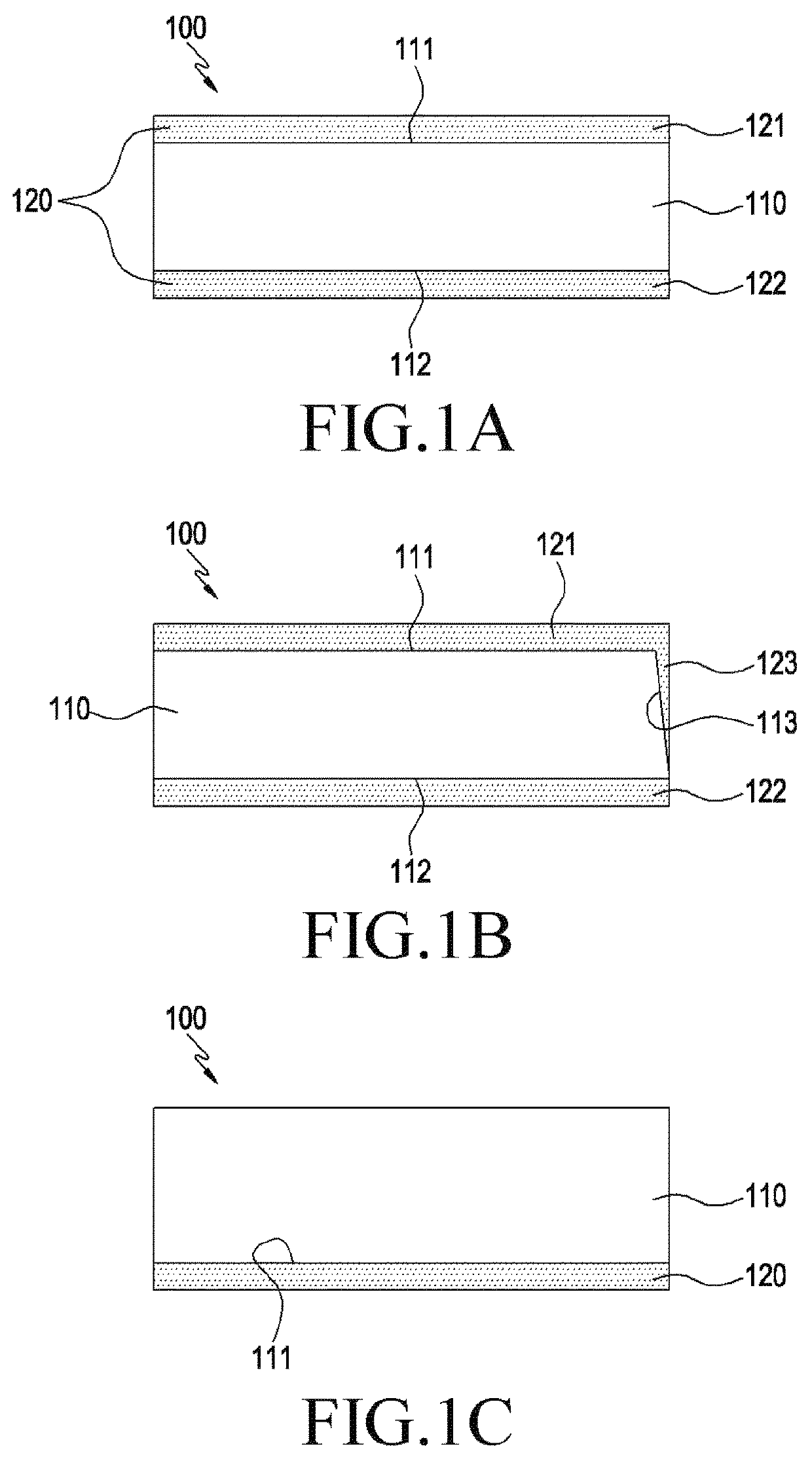
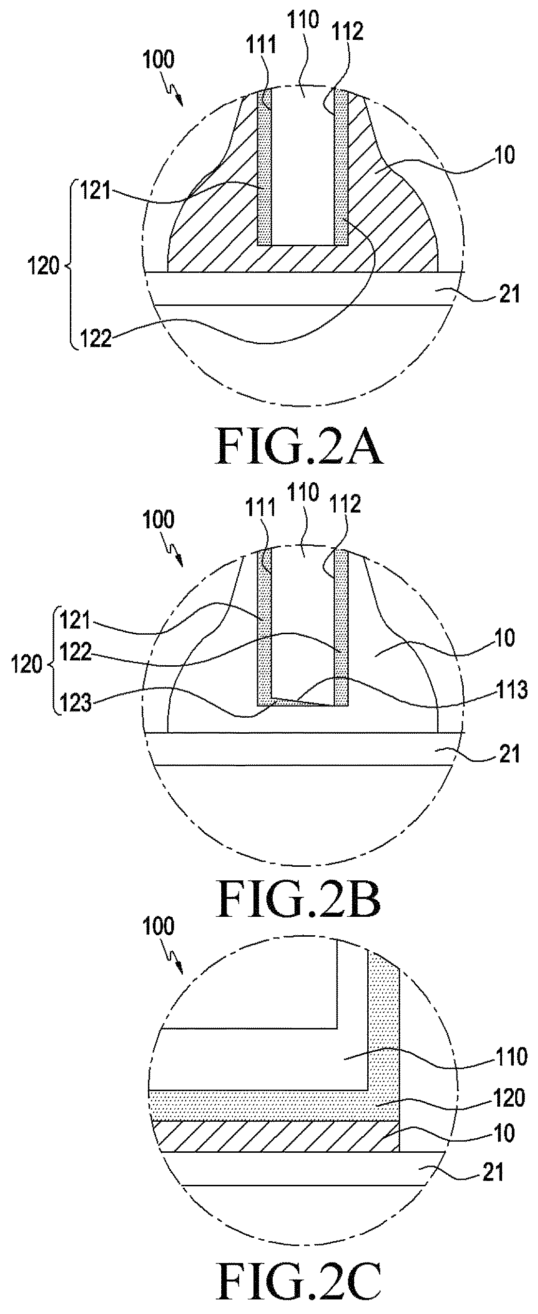
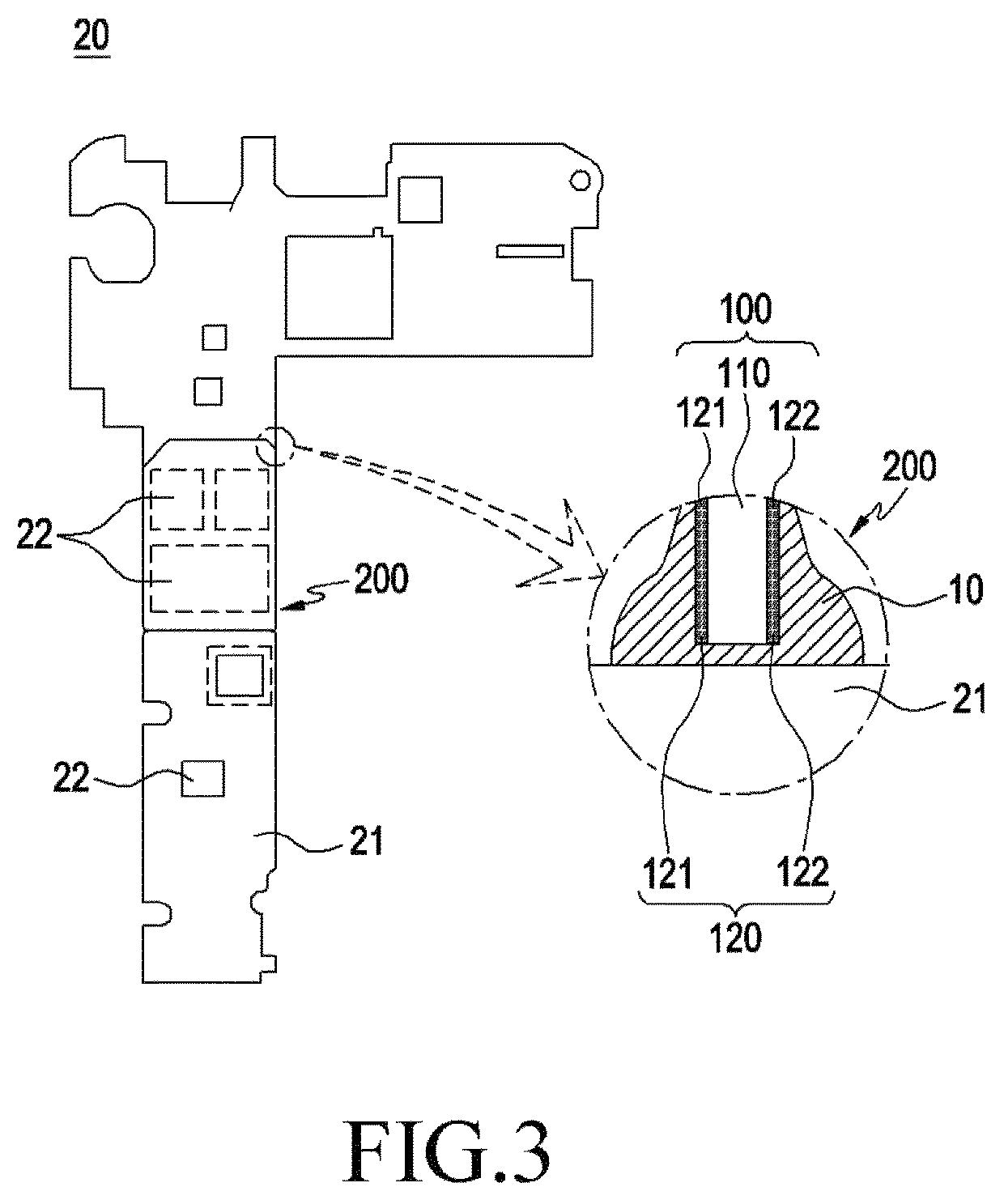
[0034]FIGS. 1A through 12, discussed below, and the various embodiments used to describe the principles of the present disclosure in this patent document are by way of illustration only and should not be construed in any way to limit the scope of the disclosure. Those skilled in the art will understand that the principles of the present disclosure may be implemented in any suitably arranged system or device.

[0035]As the present disclosure allows for various changes and numerous embodiments, some exemplary embodiments will be described in detail with reference to the accompanying drawings. However, the embodiments do not limit the present disclosure to a specific implementation, but should be construed as including all modifications, equivalents, and replacements included in the spirit and scope of the present disclosure.

[0036]Although ordinal terms such as “first” and “second” may be used to describe various elements, these elements are not limited by the terms. The terms are used m...


PUM

PropertyMeasurementUnit
tensile strengthaaaaaaaaaa
temperatureaaaaaaaaaa
thicknessaaaaaaaaaa

Abstract

According to various embodiments of the present disclosure, a metal unit may include: a core metal layer that is mainly composed of iron (Fe); and an outer layer formed on at least one face of the core metal layer, and bonded to solder so as to be attached to a printed circuit board. The metal unit and an electronic device including the same may be variously implemented according to embodiments.

Description

CROSS-REFERENCE TO RELATED APPLICATION[0001]This application is based on and claims priority under 35 U.S.C. § 119 to Korean Patent Application No. 10-2017-0038771 filed on Mar. 27, 2017, in the Korean Intellectual Property Office, the disclosure of which is incorporated by reference herein in its entirety.BACKGROUND[0002]1. Field[0003]Various embodiments of the present disclosure relate to a surface mount metal unit, and an electronic device including the same.[0004]2. Description of the Related Art[0005]An electronic device, such as a portable terminal, may be provided with a printed circuit board on which components for implementing various functions of the electronic device may be mounted. Various component elements, for example, electronic components, such as a transistor, a diode, a resistor, and an integrated circuit chip, and mechanical components, such as a SIM card socket and a shield can may be mounted on a printed circuit board.SUMMARY[0006]Mechanical components mounted ...

Claims


Application Information

Patent Timeline
Patent Type & Authority Patents(United States)
IPC IPC(8): H05K1/09H05K1/18H05K3/30H05K9/00H05K1/03C22C9/06C22C38/40C22C9/04B23K35/26B23K35/02B32B15/01H05K3/34H05K1/05H05K1/02B23K101/42
CPCH05K3/303C22C38/40C22C9/04C22C9/06H05K1/0306H05K3/341H05K9/0049B32B15/013H05K1/053H05K1/181H05K9/0028B23K35/262B32B15/018B23K35/0238H05K2201/10371Y02P70/613B23K2101/42H05K2201/10318H05K1/0216H05K2201/10333Y02P70/50H05K9/0084H05K3/3457
Inventor LEE, CHANG-JOONLEE, YONG-WONJANG, HYUN-TAE
Owner SAMSUNG ELECTRONICS CO LTD
Why Eureka
Try Eureka