Packing, method for manufacturing same, and liquid film-forming structure

a technology of liquid film and packaging, which is applied in the directions of transportation and packaging, separation processes, chemical/physical/physicochemical processes, etc., can solve the problems of increasing the difficulty of making the net-like body stand-alone, and the increase in the weight and size of the apparatus. , to achieve the effect of suppressing pressure loss and good energy efficiency during operation

Active Publication Date: 2021-10-26
IHI CORP +1
View PDF22 Cites 0 Cited by
  • Summary
  • Abstract
  • Description
  • Claims
  • Application Information

AI Technical Summary

Benefits of technology

[0011]However, it takes time and labor to process the packing disclosed in each of the Publication Documents 1 to 3, and manufacturing cost of the packing is greatly increased. Particularly, since a net-like body such as wire gauze and three-dimensional knitted fabrics has insufficient strength and distortion of the shape thereof is easy, it is difficult to make the net-like body stand-alone. Therefore, a support member having strength is required when performing the treatment with the net-like body in a standing state, and thus weight increase due to it causes on the support structure of the packing, that leads to an increase in the weight and the size of the apparatus, increasing material costs and manufacturing costs.
[0014]The present disclosure has come to create in view of the above-described problems. An object of the present disclosure is to provide a packing for gas-liquid contact and a manufacturing method therefor, capable of realizing preferable gas-liquid contact and efficient component transfer, with suppressing pressure loss in gas-liquid contact while eliminating wetting inhibition caused by the structure.
[0021]It is possible to obtain a packing for gas-liquid contact, capable of suppressing pressure loss in gas-liquid contact while realizing preferable gas-liquid contact and efficient component transfer, and it becomes possible to provide a gas-liquid contact apparatus having good energy efficiency during operation.

Problems solved by technology

However, it takes time and labor to process the packing disclosed in each of the Publication Documents 1 to 3, and manufacturing cost of the packing is greatly increased.
Particularly, since a net-like body such as wire gauze and three-dimensional knitted fabrics has insufficient strength and distortion of the shape thereof is easy, it is difficult to make the net-like body stand-alone.
Therefore, a support member having strength is required when performing the treatment with the net-like body in a standing state, and thus weight increase due to it causes on the support structure of the packing, that leads to an increase in the weight and the size of the apparatus, increasing material costs and manufacturing costs.
In addition, in a structure in which a flow path of a gas flowing in a packing has a complicated shape, the packing hinders the gas flow and pressure loss increases, resulting in lowering of energy efficiency in gas supply.
However, with the structure disclosed in this document, it is difficult to supply the liquid accurately to the entire packing and it tends to be uneven supply.
Therefore, the absorbing liquid flowing down the packing may concentrate locally, and increasing gas-liquid contact area is unexpectedly difficult.
In addition, the structure is not very high in uniformity in space utilization, and there is little room for improvement even in the gas-liquid contact area per filling volume.
However, even in this case, if attaching a reinforcing material for convenience of material selection and structural design, it is necessary to resolve the problem of a decrease in the gas-liquid contact surface area and the problem caused in wetting by a liquid, caused due to presence of the reinforcing material.

Method used

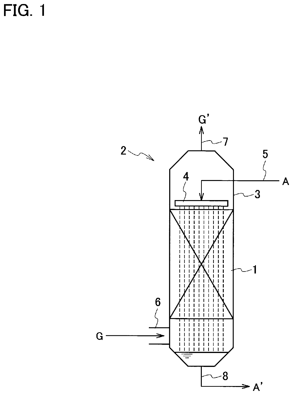
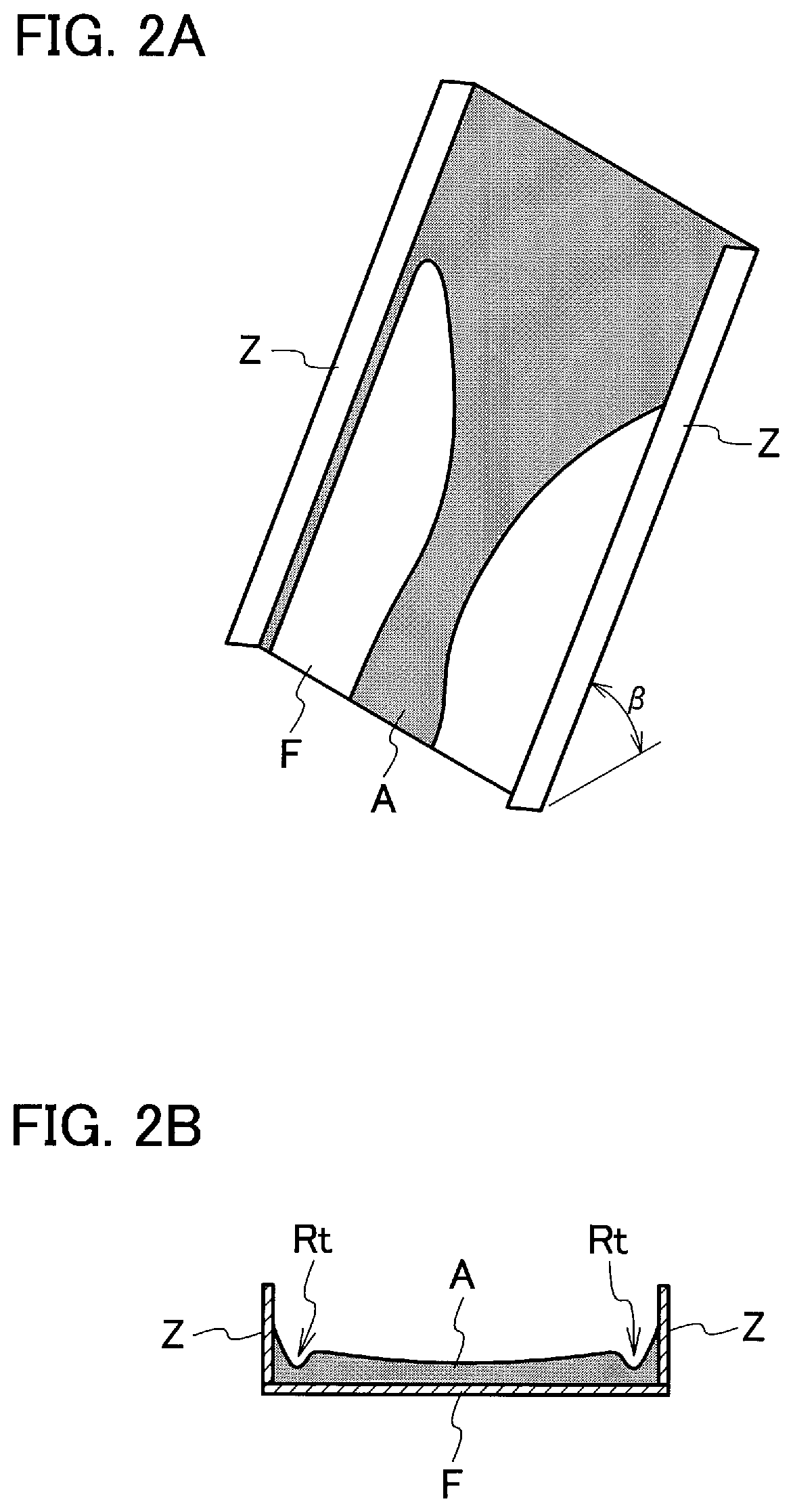
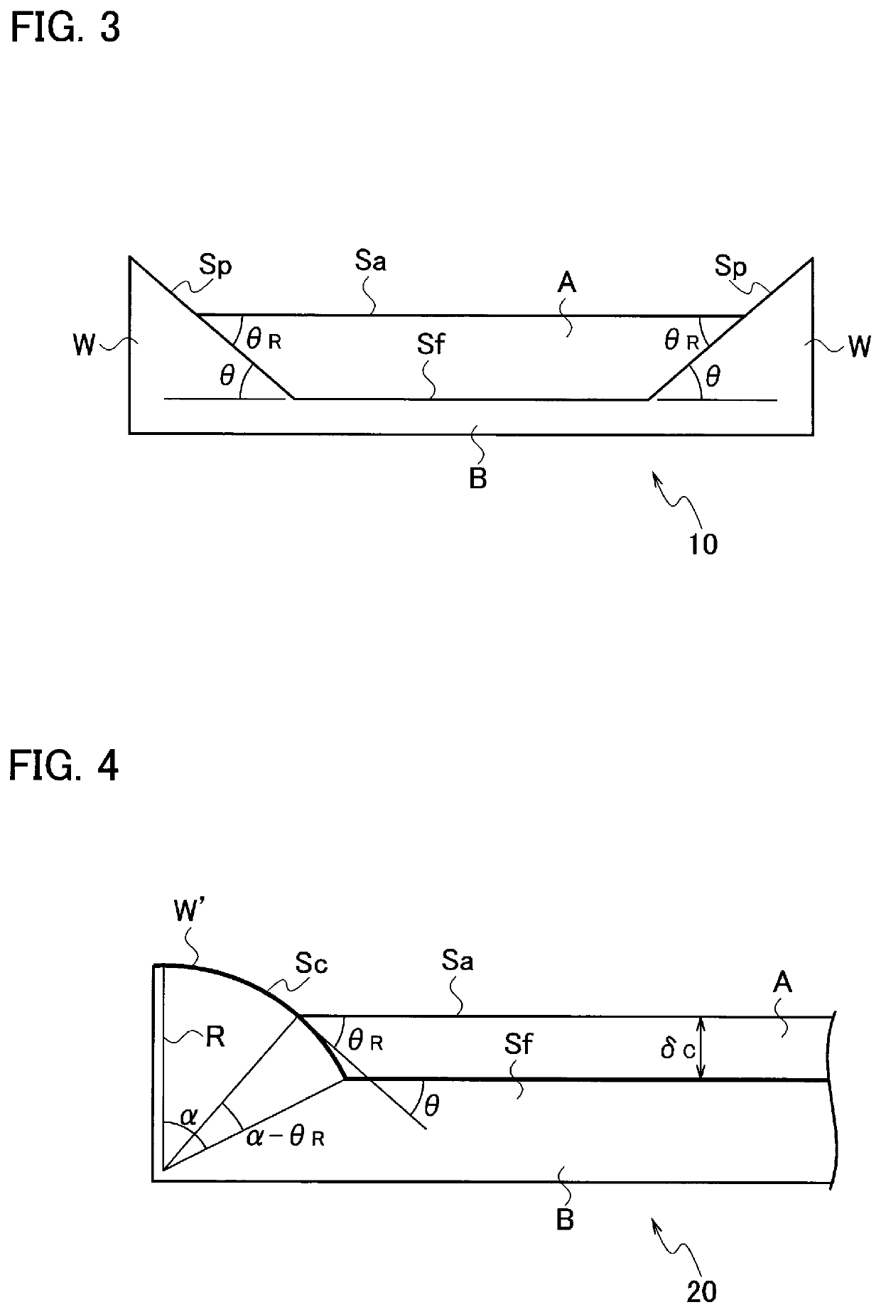

Image

  • Packing, method for manufacturing same, and liquid film-forming structure
  • Packing, method for manufacturing same, and liquid film-forming structure
  • Packing, method for manufacturing same, and liquid film-forming structure

Examples


examples

[0113]

[0114]A flat plate material made of stainless steel (SUS304) having a length of 60 mm was prepared, and a flow channel having a rectangular cross section (lateral width <50 mm, depth <5 mm) was formed along the longitudinal direction of the flat plate material. This work was carried out by scraping by electric discharge machining and finishing with an end mil having a diameter of 20 mm. Further, using the end mill, processing was applied to the bottom surface and the side surfaces of the flow channel. Thereby, it was finish into a shape having a lateral width of 50 mm and a depth of 5 mm and having a flat surface inclined at an inclination angle θ (exterior angle with respect to the bottom surface) of 20° (Sample S1) or 25° (Sample S2) on both sides of the bottom surface of the flow channel. It was used as a packing element of Sample S1 or Sample S2 in the following measurement.

[0115]

[0116]A flat plate material made of stainless steel (SUS304) having a length of 60 mm was prep...


PUM


Abstract

A packing for gas-liquid contact has at least one packing element of a thin layer shape, placed in a standing position. The packing element has a main body portion having a planar liquid film-forming surface extending along a liquid flow direction, and at least one wall portion provided to stand relative to the liquid film-forming surface and extending along the liquid flow direction. The wall portion has a side surface inclined at a predetermined angle to the liquid film-forming surface in a surface position of a liquid film to be formed by a liquid on the liquid film-forming surface.

Description

CROSS REFERENCE TO RELATED APPLICATIONS[0001]This application is a continuation application of International Application No. PCT / JP2019 / 002933, filed on Jan. 29, 2019, which claims priority of Japanese Patent Application No. 2018-013603, filed on Jan. 30, 2018, the entire contents of which are incorporated by reference herein.BACKGROUNDTechnical Field[0002]The present disclosure relates to a packing for promoting mass transfer between gas and liquid in gas-liquid contact, a method for manufacturing the same, and a liquid film-forming structure.Description of the Related Art[0003]Conventionally, a gas separation apparatus employing gas-liquid contact is used in chemical plants, thermal power plants and the like, to separate, remove or recover a specific gas from a gas to be treated, containing various kinds of gases, such as an exhaust gas. For example, in a carbon-dioxide recovering apparatus, a gas containing carbon dioxide gets into contact with an absorbent such as an aqueous mon...

Claims


Application Information

Patent Timeline
Patent Type & Authority Patents(United States)
IPC IPC(8): B01D53/18B01F3/04B01J19/32
CPCB01D53/18B01F3/04078B01F3/04475B01F3/04489B01J19/32B01J2219/3221B01J2219/32227B01J2219/32248B01J2219/32206B01J2219/32258B01J2219/32262B01J2219/3325B01J19/247Y02C20/40B01F23/214B01F23/23211B01F23/232112
Inventor ISO, YOSHIYUKIIKEDA, RYOSUKETAKANO, KENJIKATOH, KENJIWAKIMOTO, TATSURO
Owner IHI CORP
Why Eureka
Try Eureka