Method for monitoring a mechanical system

a mechanical system and monitoring method technology, applied in the direction of testing/monitoring control systems, process and machine control, etc., can solve the problems of affecting the operation of the system, the combination of valve and drive regularly being stuck in the end position, and the valve may no longer be safe to close. , to achieve the effect of reducing material and reducing the amount of expenditur

Active Publication Date: 2022-06-14
SIEMENS AG
View PDF22 Cites 0 Cited by
  • Summary
  • Abstract
  • Description
  • Claims
  • Application Information

AI Technical Summary

Benefits of technology

[0017]It is the object of the present invention to provide a method for monitoring a system with mechanically movable parts, which can be performed with comparatively little material and required expenditure and which enables an extensive acquisition of a technical status of the system.
[0024]The technical device used for acquiring the indicators may be realized on the basis of the evaluation of the data outside the system in a simple manner with minimal hardware outlay. The evaluation unit may advantageously monitor a plurality of systems and, in this context, categorize the systems, for example, according to valve type, process conditions and location in a technical plant. As a result, individual valve types, which in some circumstances have frequent failure times, can be identified in a simple manner and corresponding measures may be introduced. By categorizing the valve systems monitored by the evaluation unit, it is thus possible for systematic errors in the valve systems, which regularly arise in a particular type of valve system, to be identified and corrected in a simpler manner.
[0029]Particularly preferably, an idle state of the sensors is ended by a switching procedure of the valve system, in order to initiate the acquisition of the indicators. In other words, the sensors are “woken” from an energy-saving mode by the switching procedure. The sensors are then only used when they are also actually required. As a result, the sensors can be operated in a more energy-efficient manner.
[0030]Advantageously, the transfer of the acquired indicators to the evaluation unit is linked with an identification of an opening procedure and / or closing procedure of the valve, the drive and / or the pilot valve, in order to minimize a communication effort for the evaluation unit. In other words, the acquired data is then only transferred to the evaluation unit, even if a switching procedure (opening or closing) actually occurs in the valve system.
[0041]With the foregoing information, the evaluation unit may then predict a possible maintenance requirement automatically and warn the operator before they perform a planned maintenance. In this way, early failures that emerge before the next planned maintenance can be identified and unplanned downtimes can be avoided.

Problems solved by technology

If one of the springs breaks, however, then the valve may no longer be safely closed in the event of a fault.
Thus, the regions before and after the valve may no longer be reliably separated from one another, which may lead to serious consequences.
Due to the valve and drive remaining in their end position for a long time, the combination of valve and drive regularly tends to be stuck in an end position.
Over the course of a lifecycle of the valve, the breakaway torque increases, due to wear and corrosion of the drive.
Here, the cut-off procedure may no longer be performed safely, whereby significant damage may occur.
During the opening, the same phenomena arise in an analogous manner, wherein the breakaway torque may be substantially greater, in particular with metallically sealing valves, meaning that the maximum pressure of the pneumatic auxiliary power with a given membrane surface in the drive is no longer sufficient to open the valve, which likewise may lead to considerable damage.
A further pattern of damage results from a leak in the body of the valve.
This may result in chemically aggressive or highly reactive media escaping, where applicable, which may cause damage.
The previously explained patterns of damage in valves typically used in the process industry, therefore, cannot be detected, or can only be detected with a comparatively high level of expense.
A safe operation of valves, in particular on / off valves, has therefore only been possible to date via regular checking and maintenance or by redundant installations (one or more redundant valves) or by overdimensioning of individual elements of the valves, for example, by using more powerful springs, or by additional and therefore uneconomical diagnostics apparatuses from the field of regulating valves (e.g., what are known as positioners, which may exceed the investment costs of a switching valve many times over).
In the absence of suitable, cost-effective diagnostics instruments, the valves are disassembled every five years for maintenance purposes, for example, which causes comparatively high service costs and plant shutdowns.
In the case of a retrofit, high conversion expenses are also called for.
This leads to this technology being virtually unused.
This, however, requires a high level of expense for additional material, which would not be necessary for the actual process automation.
Additional local information relating to a status of the valves can therefore only be obtained with a high additional expense.
This data, however, may only be used to an insufficient extent for characterizing a status of the valve.

Method used


Image

  • Method for monitoring a mechanical system
  • Method for monitoring a mechanical system

Examples


Embodiment Construction

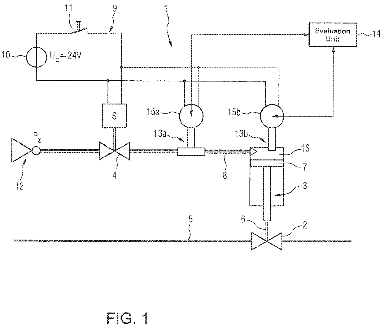
[0046]FIG. 1 shows a valve system 1. The valve system 1 comprises a process valve 2, a pneumatic drive 3 and a pilot valve 4.

[0047]A medium flowing through a process line 5 is controlled by the process valve 2. The process valve 2 involves an open / close valve (on / off valve), which can be switched between the two statuses “valve open” and “valve closed”.

[0048]The switching of the process valve 2 occurs via the pneumatic drive 3. A membrane 7 coupled with a valve spindle 6 of the process valve 2 is moved in the pneumatic drive 3 in a known manner via compressed air guided through a compressed air line 8. In FIG. 1, the pneumatic drive 3 is shown as a representative of the conventional, known forms of embodiments without resetting springs. The process valve 2 may have all known configurations, such as “normally open” or “normally close”, “single-acting” or “double-acting”.

[0049]The pilot valve 4 is supplied with electrical power via an electrical supply network 9. The electrical supply...


PUM


Abstract

A method for monitoring a system with mechanically movable parts, preferably a valve system, wherein the system is preferably part of a technical plant, in particular a production plant, and wherein the system has at least one mechanically movable part, in particular a valve, where the method comprises a) acquiring indicators, which can be used for a technical characterization of a movement procedure of the mechanically movable part, via technical devices configured for the acquisition of the indicators and b) transferring the acquired indicators to an evaluation unit arranged outside the system to determine a technical status of the system.

Description

BACKGROUND OF THE INVENTION1. Field of the Invention[0001]The invention relates to a method for monitoring a system with mechanically movable parts.2. Description of the Related Art[0002]In the process industry, valves are opened with the aid of pneumatic drives and pneumatic auxiliary power, for example. In this context, spring packages in the drive ensure that the valve is closed in the event of a failure of the pneumatic auxiliary power. If one of the springs breaks, however, then the valve may no longer be safely closed in the event of a fault. Thus, the regions before and after the valve may no longer be reliably separated from one another, which may lead to serious consequences.[0003]Valves are largely used for temporary cutting-off / opening. As a result, they are situated in an open / closed status over comparatively long periods of time, in order to only be closed / opened via a drive and pneumatic auxiliary power on demand. Due to the valve and drive remaining in their end posit...

Claims


Application Information

Patent Timeline
Patent Type & Authority Patents(United States)
IPC IPC(8): F16K37/00F16K31/126F16K31/124F16K31/122F16K31/128G06Q10/00
CPCF16K37/0083F16K31/124F16K31/128F16K31/1221F16K31/1262F16K37/0041F16K37/0075F16K37/0091G06Q10/20Y10T137/8242Y10T137/8326F16K37/00G05B23/0235F16K31/122F15B19/005F15B2211/6313F15B2211/6303
Inventor BARTH, JOHANNESHUCK, RALF
Owner SIEMENS AG
Why Eureka
Try Eureka