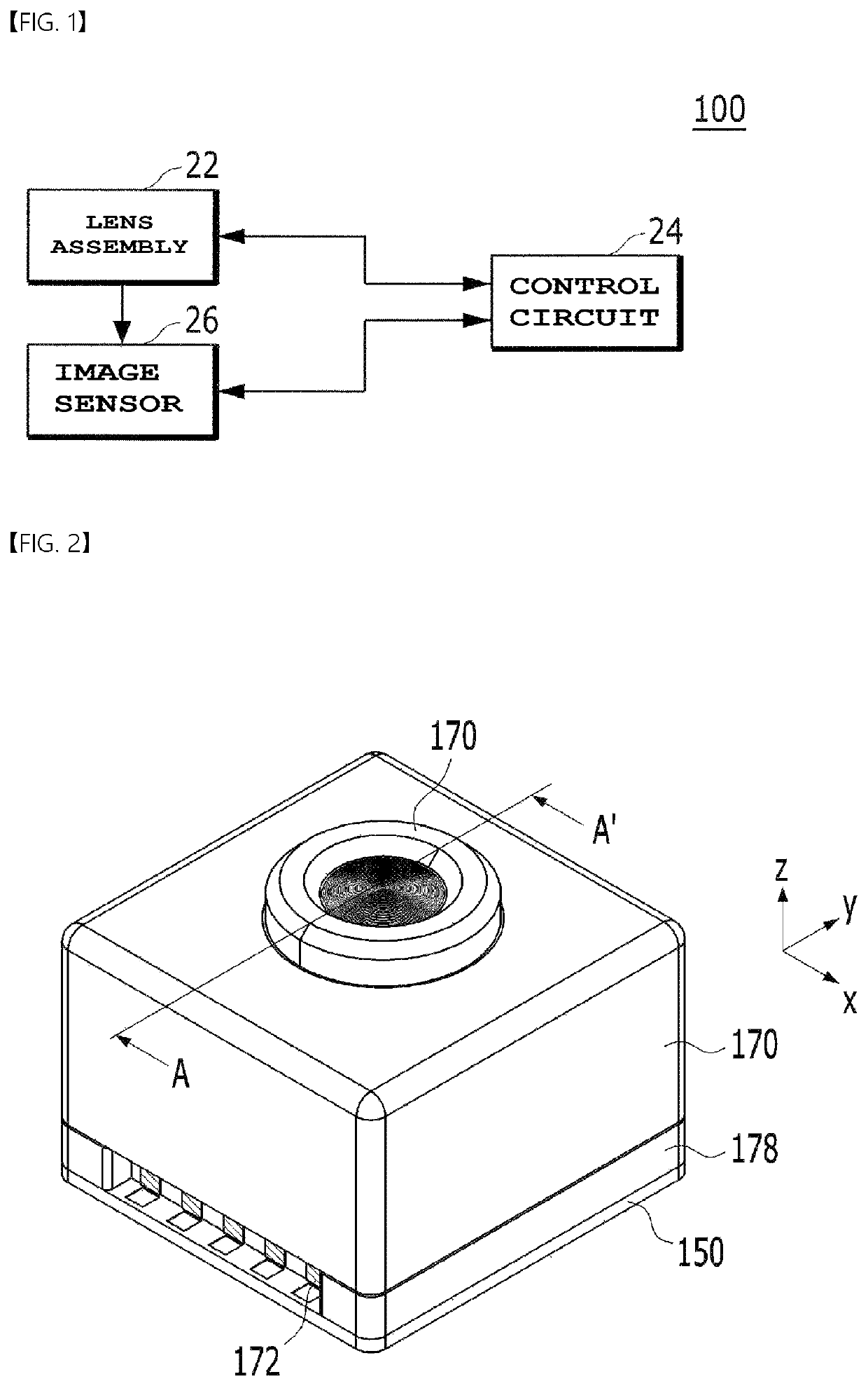
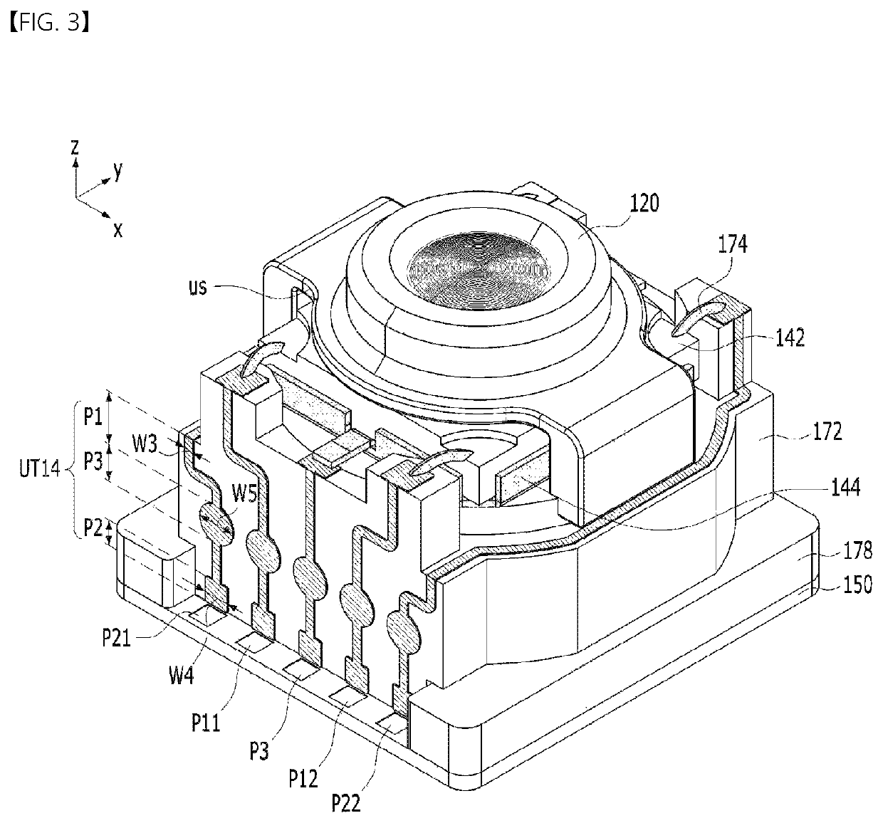
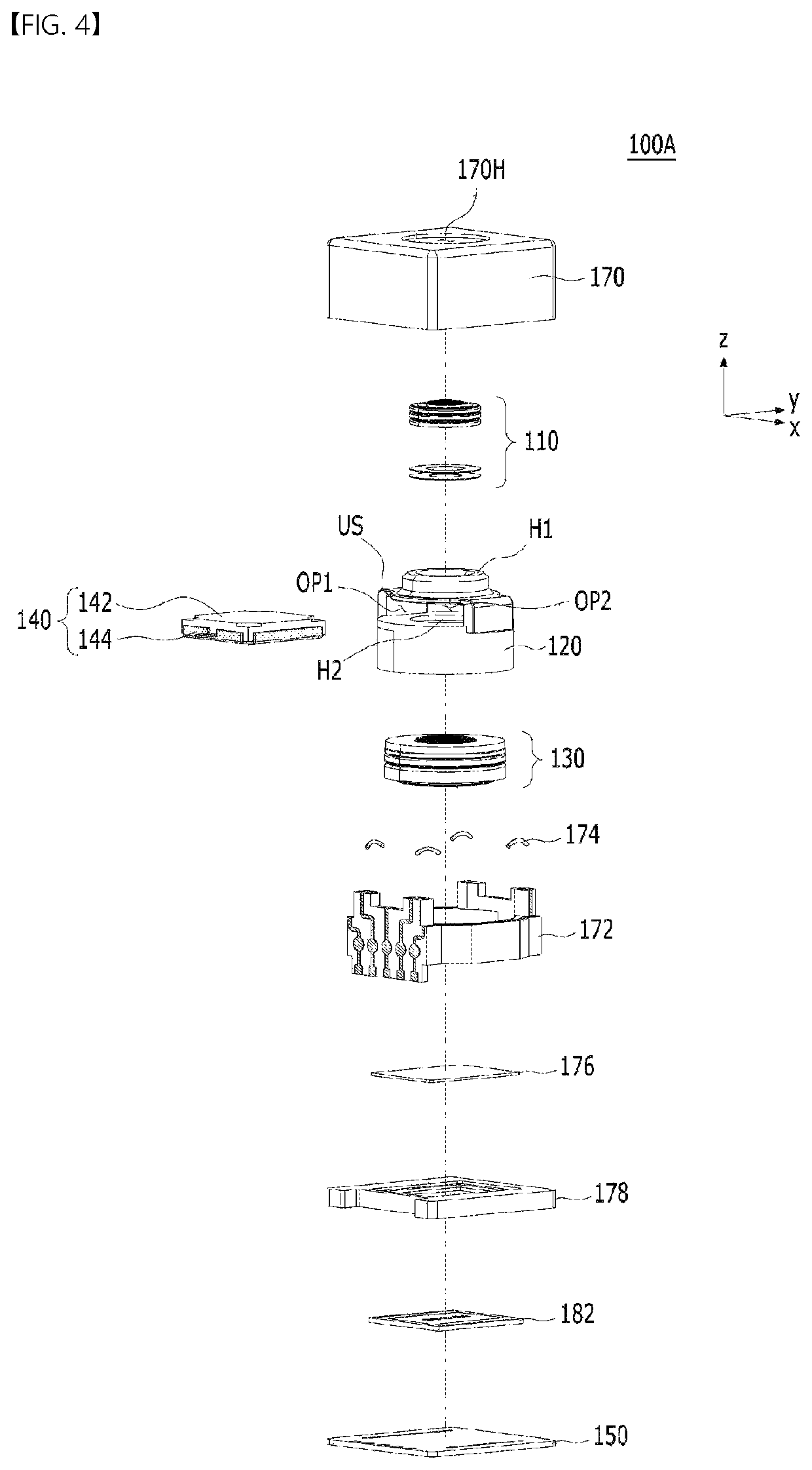
Camera module
a technology of camera module and camera body, which is applied in the direction of camera focusing arrangement, printers, instruments, etc., can solve the problems of high power consumption of the lens moving apparatus and the increase of the overall size of the conventional camera module, so as to reduce manufacturing time and cost, improve tolerance accuracy, and achieve the effect of electrical connection between the lower connection substrate and the main board more reliably
Active Publication Date: 2022-06-14
LG INNOTEK CO LTD
View PDF23 Cites 2 Cited by
- Summary
- Abstract
- Description
- Claims
- Application Information
AI Technical Summary
Benefits of technology
The camera module described in this patent reduces manufacturing time, costs, and complexity by eliminating the need for a flexible printed circuit board (FPCB) and a spacer to protect the lens. Instead, a lower connection substrate is used to protect the lens and facilitate electrical connection between the main board without the need for bending of the FPCBs. This design also improves tolerance and reliability, reduces the size of the module, and simplifies the manufacturing process. Overall, this innovation provides a more efficient and cost-effective camera module with improved performance and reliability.
Problems solved by technology
However, the lens moving apparatus has high power consumption, and an additional cover glass needs to be provided separately from a camera module in order to protect the lens moving apparatus, thus causing a problem in that the overall size of the conventional camera module increases.
Method used
View moreImage
Smart ImageViewing Examples
Examples
Embodiment Construction
[0210]Various embodiments have been described in the best mode for carrying out the disclosure.
INDUSTRIAL APPLICABILITY
[0211]A camera module according to embodiments may be used in camera / video devices, telescopic devices, microscopic devices, an interferometer, a photometer, a polarimeter, a spectrometer, a reflectometer, an auto-collimator, a lens-meter, a smartphone, a laptop computer, a tablet computer, etc.
Login to View More PUM
 Abstract
A camera module includes a liquid lens unit; a lens holder in which the liquid lens unit is disposed; a main board configured to supply a driving signal to drive the liquid lens unit; and a base disposed on the main board, the base having an inner space in which the liquid lens unit is disposed, wherein the liquid lens unit includes: a liquid lens including upper electrodes and a lower electrode; and a lower connection substrate connected to the lower electrode, and wherein the base includes: an upper connection part configured to electrically connect the upper electrodes to the main board, the upper connection part being disposed adjacent to the upper electrodes in a plan view; and a lower connection part configured to electrically connect the lower connection substrate to the main board.
Description
CROSS REFERENCE TO RELATED APPLICATIONS[0001]This application is the National Phase of PCT International Application No. PCT / KR2019 / 000828, filed on Jan. 21, 2019, which claims priority under 35 U.S.C. 119(a) to Patent Application No. 10-2018-0008346, filed in the Republic of Korea on Jan. 23, 2018, all of which are hereby expressly incorporated by reference into the present application.TECHNICAL FIELD[0002]Embodiments relate to a camera module.BACKGROUND ART[0003]People who use portable devices demand optical devices that have high resolution, are small, and have various photographing functions. For example, these various photographing functions may be at least one of an optical zoom-in / zoom-out function, an auto-focusing (AF) function, or a hand-tremor compensation or optical image stabilizer (OIS) function.[0004]In a conventional art, in order to implement the above-described various photographing functions, a method of combining a plurality of lenses and directly moving the comb...
Claims
Login to View More Application Information
Patent Timeline
 Patent Type & Authority Patents(United States)
IPC IPC(8): H04N5/225G02B7/02G03B17/12
CPCH04N5/2257G02B7/02G03B17/12G03B30/00G03B3/10G03B5/00G03B2205/0084G03B2217/005G02B27/646G02B3/14G02B7/08G02B13/001H04N23/57H04N23/55H05K1/141G02B7/04G03B2217/007
Inventor SONG, YUN SANGKIM, IN TAEBAIK, JUNG SHIK
Owner LG INNOTEK CO LTD
Features
- R&D
- Intellectual Property
- Life Sciences
- Materials
- Tech Scout
- Unparalleled Data Quality
- Higher Quality Content
- 60% Fewer Hallucinations
Learn More Browse by: Latest US Patents, China's latest patents, Technical Efficacy Thesaurus, Application Domain, Technology Topic, Popular Technical Reports.
© 2025 PatSnap. All rights reserved.Legal|Privacy policy|Modern Slavery Act Transparency Statement|Sitemap|About US| Contact US: help@patsnap.com


