
Coil unit

a coil unit and coil technology, applied in the direction of transformer/inductance coil/winding/connection, inductance, transportation and packaging, etc., can solve the problems of reducing the amount and possibly reducing so as to improve the efficiency of wireless charging. the effect of improving the coefficient of coupling between the coil unit and the wireless charging system

Active Publication Date: 2022-06-21
TOYOTA JIDOSHA KK
View PDF20 Cites 0 Cited by
  • Summary
  • Abstract
  • Description
  • Claims
  • Application Information

AI Technical Summary

Benefits of technology

This design enhances the coefficient of coupling, improving wireless charging efficiency by ensuring more magnetic flux is incident on the exposed part of the ferrite, thereby increasing the efficiency of power transfer between coil units.

Problems solved by technology

This may reduce the amount of magnetic flux coming around to and incident on the exposed part, thus possibly reducing the coefficient of coupling.

Method used


Image

  • Coil unit
  • Coil unit
  • Coil unit

Examples


Embodiment Construction

[0028]Hereinafter, the present embodiment is described in detail with reference to the drawings. In the drawings, identical or corresponding parts are identically denoted, and the explanation thereof is not repeated.

[0029]

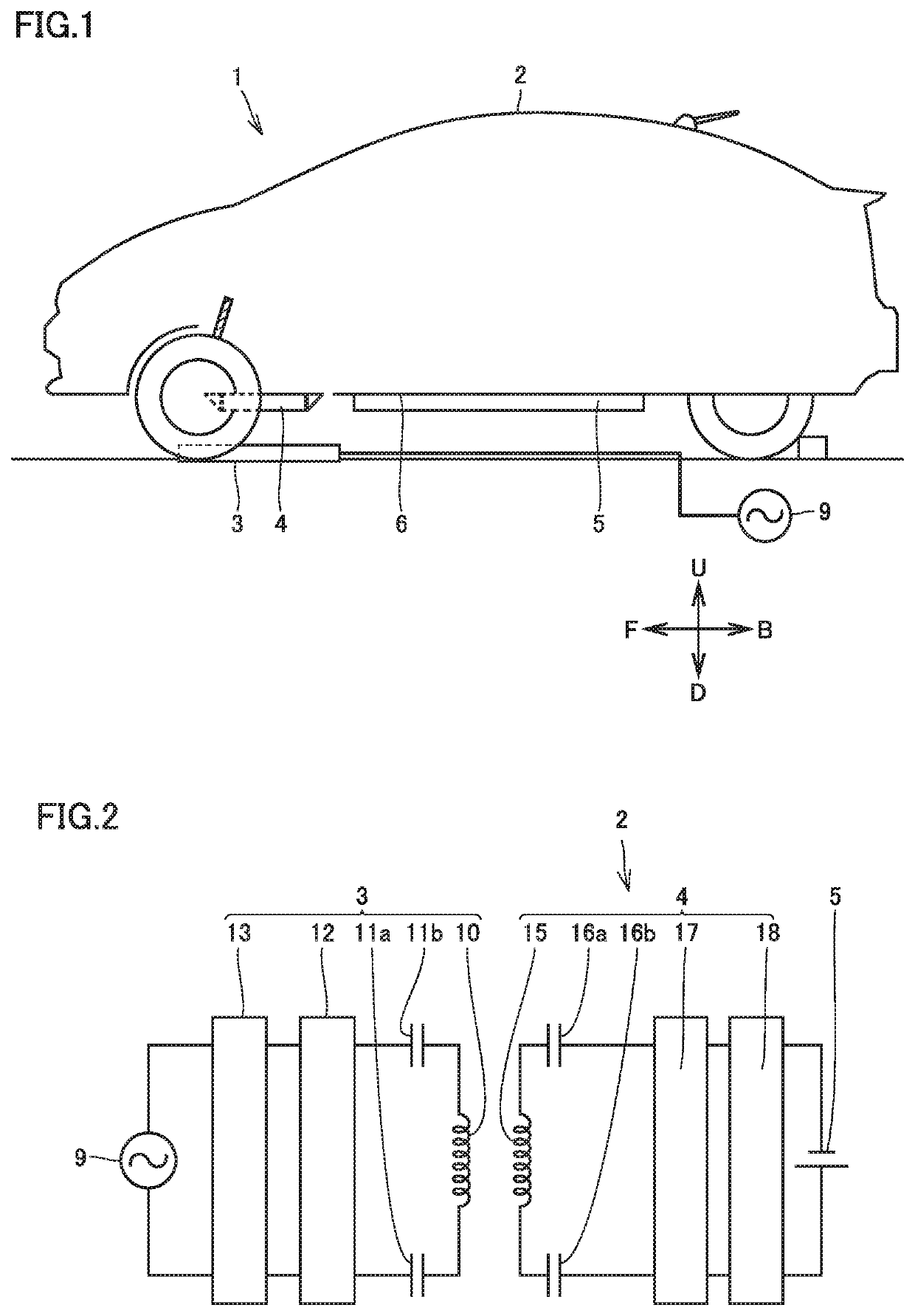
[0030]FIG. 1 is a general view of a wireless charging system according to the present embodiment. With reference to FIG. 1, a wireless charging system 1 includes a vehicle 2 and a power-transmission-side coil unit 3. Power-transmission-side coil unit 3 is installed on the ground.

[0031]Hereinafter, in a parking space where power-transmission-side coil unit 3 is installed, the direction of movement of vehicle 2 is defined as F and B directions, and the up and down directions relative to the ground are respectively defined as U and D directions. Although not shown in FIG. 1, the right and left directions relative to vehicle 2 in a parking space are respectively defined as R and L directions. Hereinafter, the U direction may be simply referred to as “upper side”, “uppe...


PUM

PropertyMeasurementUnit
lengthaaaaaaaaaa
magnetic fluxaaaaaaaaaa
transparentaaaaaaaaaa

Abstract

A power-reception-side coil unit includes: a housing, a ferrite, a power reception coil, a shield, and a metal member. The metal member includes a peripheral wall, a partition wall, and a shield. The ferrite includes a first principal surface, and a second principal surface. The power reception coil is provided on the side of the second principal surface, and the shield is provided on the side of the first principal surface. The shield has an outer peripheral edge including a step portion extending away from the first principal surface. The ferrite includes an exposed part exposed through the shield by forming the step portion. In the separation direction from the outer peripheral edge of the ferrite plate to the metal member, the length from the outer peripheral edge of the ferrite plate to the metal member is longer than the length of the exposed part.

Description

CROSS REFERENCE TO RELATED APPLICATIONS[0001]This nonprovisional application claims priority to Japanese Patent Application No. 2018-193071 filed on Oct. 12, 2018 with the Japan Patent Office, the entire contents of which are hereby incorporated by reference.BACKGROUNDField[0002]The present disclosure relates to a coil unit for use in wireless power transmission.Description of the Background Art[0003]Japanese Patent Laid-Open No. 2016-103589 discloses a power-reception-side coil unit and a power-transmission-side coil unit (which may also be referred to as a “coil unit” as a general term when there is no need to distinguish them) for use in, a wireless charging system. The coil unit includes a ferrite, a coil, a shield for blocking an electromagnetic wave generated by the coil, and a housing containing these components. The housing is composed of a metal housing body and a resin cover covering the housing body. The shield is provided on a first principal surface of the ferrite, and ...

Claims


Application Information

Patent Timeline
Patent Type & Authority Patents(United States)
IPC IPC(8): H01F27/02H01F27/36H01F27/28H01F38/14
CPCH01F27/36H01F27/02H01F27/28H01F38/14H01F5/00H01F5/04H01F27/363Y02T10/70
Inventor YUASA, HIROAKI
Owner TOYOTA JIDOSHA KK
Learn More