Aircraft propulsion assembly provided with a rotary transformer for supplying the blades with electrical energy

a technology of rotary transformer and blades, which is applied in the direction of propellers, inductances, transportation and packaging, etc., can solve the problems of limited transformer support force and structural modification of turbomachines

Active Publication Date: 2022-06-28
SN DETUDE & DE CONSTR DE MOTEURS DAVIATION S N E C M A +2
View PDF16 Cites 0 Cited by
  • Summary
  • Abstract
  • Description
  • Claims
  • Application Information

AI Technical Summary

Benefits of technology

[0014]Thus, by integrating the transformer directly at the level of the dynamic seal support flange in connection with the propeller shaft, the structural modifications of the turbomachine as well as the forces supported by the transformer are limited. The transformer advantageously has a reduced air gap ensuring sufficient compactness for this integration.
[0014]Thus, by integrating the transformer directly at the level of the dynamic seal support flange in connection with the propeller shaft, the structural modifications of the turbomachine as well as the forces supported by the transformer are limited. The transformer advantageously has a reduced air gap ensuring sufficient compactness for this integration.
[0016]Preferably, said stator casing is integrated into said dynamic seal support flange to form one and the same part.
[0016]Preferably, said stator casing is integrated into said dynamic seal support flange to form one and the same part.

Problems solved by technology

Thus, by integrating the transformer directly at the level of the dynamic seal support flange in connection with the propeller shaft, the structural modifications of the turbomachine as well as the forces supported by the transformer are limited.

Method used


Image

  • Aircraft propulsion assembly provided with a rotary transformer for supplying the blades with electrical energy
  • Aircraft propulsion assembly provided with a rotary transformer for supplying the blades with electrical energy
  • Aircraft propulsion assembly provided with a rotary transformer for supplying the blades with electrical energy

Examples


first embodiment

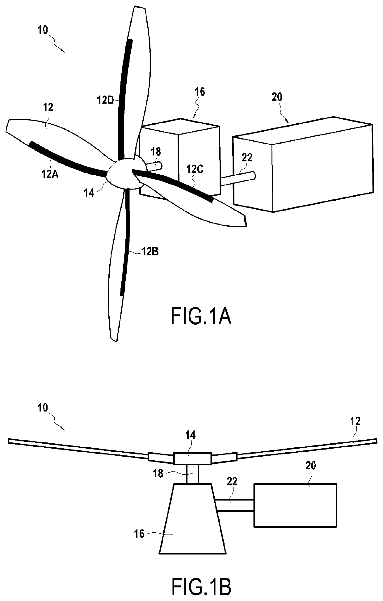
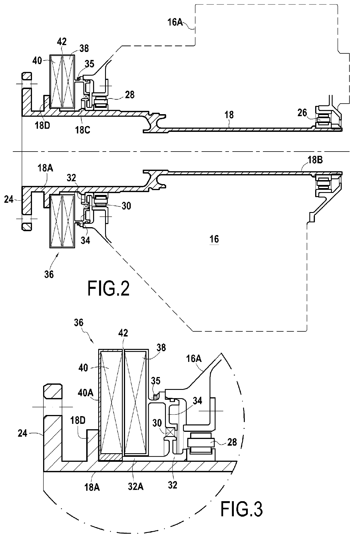
[0035]According to the invention, in order to deliver the electrical power necessary for supplying the electrical de-icing element(s), it is proposed to place the axial flow rotating transformer (TFE36) on this propeller shaft passing through the reduction gear, at the output of this reduction gear (that is to say in front of the propeller shaft, on the propeller side), between the flange 24 for fixing to the propeller and the case 16A of the reduction gear. This location is chosen rather than any other since it is present on most current reduction gear configurations since the length of the propeller shaft is conventionally constrained by the integration at this location of the “brushes+collector” system of the art prior. The transformer 36, by fitting into this available space instead of this conventional system, therefore does not require the release of an additional free volume and, depending on the dimensions of the transformer used, it becomes even possible to reduce the dista...

second embodiment

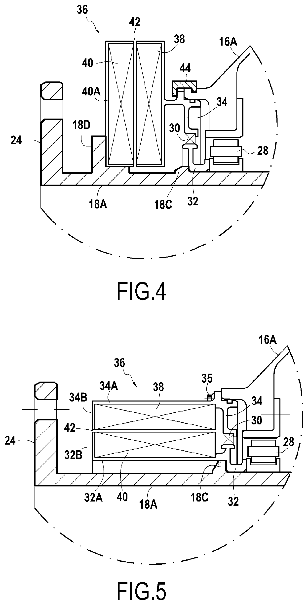
[0046]Similarly to the previous embodiment, the dynamic seal support flange 34 is modified by being extended by an axial circumferential wall 34A terminated by a radial return wall 34B to also form the casing of the stator 38 of the transformer, the assembly then constituting one and the same part. On the other hand, in this second embodiment, the rotating dynamic seal support 32 is extended in turn by an axial circumferential wall 32A terminated by a radial return wall 32B to form a casing of the rotor, the assembly constituting one and the same part held axially by clamping between the shoulder 18C of the propeller shaft 18 and the bearing 28 for supporting the propeller shaft 18. In this way, the rotor cantilevered on this shoulder rests on a small length of the propeller shaft in an area which is located closer to the roller bearing of the bearing 28 taking up the forces of the propeller shaft 18.

[0047]The advantages provided by this configuration of a TFU allowing the integrati...


PUM

PropertyMeasurementUnit
lengthaaaaaaaaaa
electrical poweraaaaaaaaaa
electricalaaaaaaaaaa

Abstract

A propulsion unit for an aircraft, including an engine and a propeller shaft and further a propeller with airfoils which is coupled to the propeller shaft and having electrical members consuming electrical power, sealing between a case and the propeller shaft being ensured by a dynamic seal housed between a rotating dynamic seal support secured to the propeller shaft and a dynamic seal support flange secured to an end portion of the case, the rotating dynamic seal support being secured to the propeller shaft and abutted against a bearing for supporting this propeller shaft, it is provided that the propulsion unit, in order to deliver electrical power to the electrical members, having a rotating transformer rotated by the propeller shaft and including a stator, a casing of which is secured to the dynamic seal support flange and a rotor, a casing of which is secured to this propeller shaft.

Description

CROSS-REFERENCE TO RELATED APPLICATIONS[0001]This application is the U.S. national phase entry under 35 U.S.C. § 371 of International Application No. PCT / FR2019 / 050795, filed on Apr. 4, 2019, which claims priority to French Patent Application No. 1853921, filed on May 7, 2018.BACKGROUND OF THE INVENTION[0002]On a conventional turboprop, the propeller is driven by a gas turbine (free turbine or linked turbine) via a reduction gear, the reduction gear placed between the propeller and the turbomachine can be of different types: with a simple gear train, with a compound gear train, harmonic drive, epicyclic, etc. Likewise, on a conventional helicopter, the main rotor which includes the airfoils of the helicopter is also driven by a gas turbine via a reduction gear consisting of a main gearbox (MGB).[0003]The propeller fitted to such a turboprop, as well as the main rotor of a helicopter, are generally equipped with a de-icing system allowing taking off the ice accumulating on the airfoi...

Claims


Application Information

Patent Timeline
Patent Type & Authority Patents(United States)
IPC IPC(8): B64D15/12H01F38/18B64C7/00B64C11/00B64D27/10B64D27/16B64D27/24
CPCB64D15/12B64C7/00B64C11/00B64D27/10B64D27/16B64D27/24B64D2221/00H01F38/18
Inventor SANTIN, MATHIEU JEAN JACQUESBECK, GUILLAUME JULIENMOREAU DE LIZOREUX, ALDRIC RENAUD GABRIEL MARIEMORELLI, BORIS PIERRE MARCELCHASTAGNIER, JEAN-MICHEL BERNARD PAULTURCHI, THOMAS
Owner SN DETUDE & DE CONSTR DE MOTEURS DAVIATION S N E C M A
Why Eureka
Try Eureka