Check patentability & draft patents in minutes with Patsnap Eureka AI!

Method for controlling, via a terminal and a server, a standby mode of a communication module of the terminal

a technology of communication module and terminal, applied in the field of telecommunications, can solve the problems of limiting the maximum throughput that can be achieved, complexity hinges, and the use of ultra-narrowband signals, and achieve the effect of -throughput wireless communication systems

Active Publication Date: 2022-07-12
SIGFOX
View PDF9 Cites 0 Cited by
  • Summary
  • Abstract
  • Description
  • Claims
  • Application Information

AI Technical Summary

Benefits of technology

The invention aims to address limitations in prior art solutions by reducing the cost and electrical consumption of high-throughput communication modules in terminals. The solution involves using a shared identification code that is shared among a group of terminals. This reduces the cost and eliminates the need for each terminal to have a separate personal identification code. The server remotely controls the activation of the communication module based on the availability of the shared identification code. Overall, the invention provides a more economical and efficient solution for high-throughput communication modules in terminals.

Problems solved by technology

The complexity hinges on the wireless access network, which must be capable of receiving signals that can be transmitted at arbitrary instants in time and on arbitrary frequencies.
By contrast, the use of ultra-narrowband signals limits the maximum throughput that can be achieved for exchanging data between a terminal and the wireless access network of a UNB wireless communication system.
However, one drawback of high-throughput wireless communication systems lies in the fact that they are accompanied, on the terminal side, by an electrical consumption that may prove to be too high for battery-operated objects.
Furthermore, the number of terminals able to be connected simultaneously, in a given zone, to a high-throughput wireless communication system is generally limited, and far lower than the number of terminals able to be served, in this same zone, by a low-throughput wireless communication system.
In addition, the associated cost is generally too high for M2M or IoT applications, insofar as each terminal has to have a personal identification code, for example an IMSI (“International Mobile Subscriber Identity”) subscriber number, enabling it to connect to the wireless access network of the high-throughput wireless communication system.
Although the electrical consumption of the high-throughput communication module may then be reduced by limiting use only to those exchanges requiring a high throughput, it may still remain too high for some battery-operated objects, in particular if the intended autonomy is long, of the order of a few years.
Furthermore, the cost associated with using the high-throughput communication module remains too high for M2M or IoT applications.
However, this solution does not address the problem of cost associated with using a high-throughput communication module for M2M or IoT applications.

Method used


Image

  • Method for controlling, via a terminal and a server, a standby mode of a communication module of the terminal
  • Method for controlling, via a terminal and a server, a standby mode of a communication module of the terminal
  • Method for controlling, via a terminal and a server, a standby mode of a communication module of the terminal

Examples


Embodiment Construction

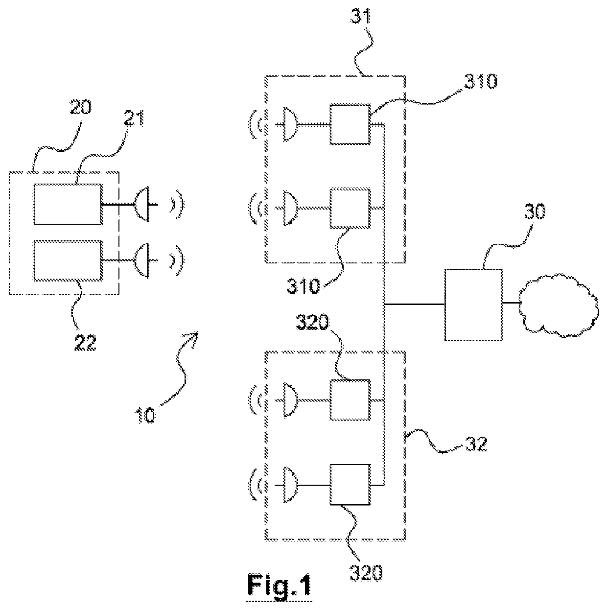
[0064]FIG. 1 schematically shows a wireless communication system 10 including a terminal 20.

[0065]The terminal 20 includes a first communication module 21 suitable for exchanging data with base stations 310 of a first wireless access network 31, and a second communication module 22 suitable for exchanging data with base stations 320 of a second wireless access network 32. In the example illustrated by FIG. 1, the base stations 310 of the first wireless access network 31 are all separate from the base stations 320 of the second wireless access network 32. However, in other examples, there is nothing to rule out having base stations belonging both to the first wireless access network 31 and to the second wireless access network 32, that is to say that are suitable for exchanging data with both the first communication module 21 and the second communication module 22.

[0066]The terminal 20 exchanges data with the first wireless access network 31 and the second wireless access network 32 ...


PUM


Abstract

A method for controlling, via a terminal, a standby mode of a first communication module of the terminal. The first communication module exchanges data with a first wireless access network. The terminal includes a second communication module, which exchanges data with a second wireless access network. The second communication module has a maximum data rate that is lower than a maximum data rate of the first communication module. The terminal belongs to a group of terminals sharing a set of one or several identification codes for connecting to the first wireless network. When the first communication module is in standby mode, the second communication module listens to a downlink between the second wireless access network and the terminal. The first communication module is activated and connects to the first wireless network using the indicated identification code in the activation request received from the server.

Description

RELATED APPLICATIONS[0001]This application is a continuation-in-part application of U.S. application Ser. No. 15 / 763,117 filed Mar. 25, 2018, which is a § 371 application from PCT / FR2016 / 052509 filed Sep. 30, 2016, which claims priority from French Patent Application No. 15 59262 filed Sep. 30, 2015, each of which is incorporated herein by reference in its entiretyTECHNICAL FIELD[0002]The present invention belongs to the field of telecommunications, and relates more particularly to the management of the electrical consumption of a terminal of a wireless communication system.BACKGROUND OF THE INVENTION[0003]The present invention is applied particularly advantageously, although without any limitation, to wireless communication systems for M2M (acronym for “Machine-to-Machine”) or “Internet of Things” (IoT) applications.[0004]In the context for example of the IoT, every everyday object is able to become a communicating object, and is equipped for this purpose with a terminal designed t...

Claims


Application Information

Patent Timeline
Patent Type & Authority Patents(United States)
IPC IPC(8): H04W52/02H04L101/654H04L101/622
CPCH04W52/0229H04L61/6022H04L61/6054H04W52/0274Y02D30/70H04L2101/654H04L2101/622
Inventor MALLART, RAOUL
Owner SIGFOX
Features
  • R&D
  • Intellectual Property
  • Life Sciences
  • Materials
  • Tech Scout
  • Unparalleled Data Quality
  • Higher Quality Content
  • 60% Fewer Hallucinations
Learn More