Mechanical filter element, apparatus and method

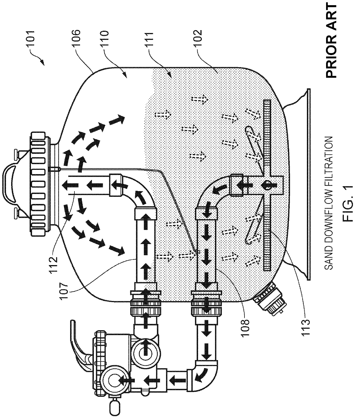
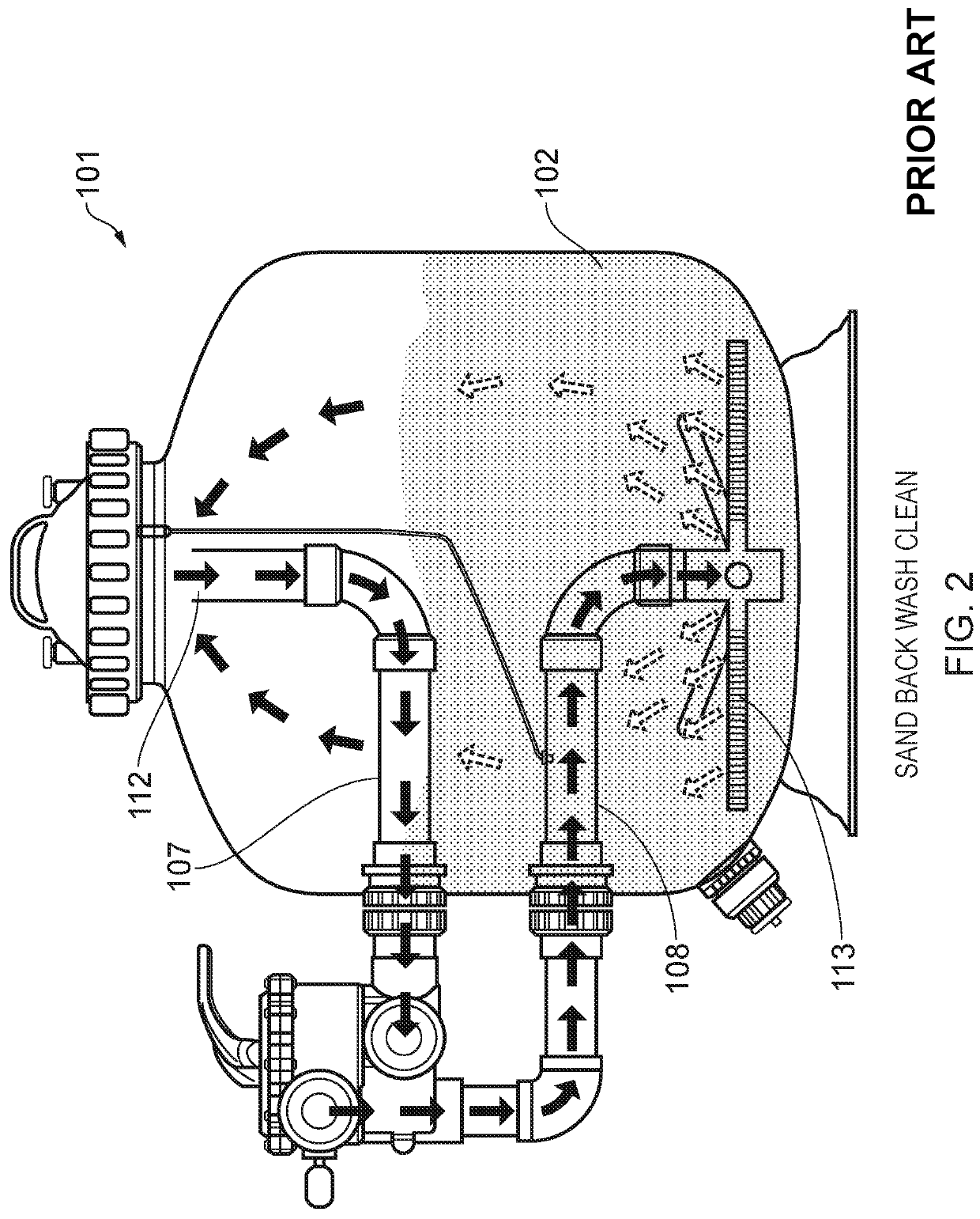
a mechanical filter and element technology, applied in the direction of filtration separation, separation process, treatment involving filtration, etc., can solve the problems of static filter bed 111/b>, bacterial problems associated with potential rise, and various known limitations of mechanical filter apparatus

Active Publication Date: 2022-07-19
EVOLUTION AQUA LTD
View PDF100 Cites 0 Cited by
  • Summary
  • Abstract
  • Description
  • Claims
  • Application Information

AI Technical Summary

Benefits of technology

[0009]Aspects of the present invention relate to a filter apparatus; a swimming pool filter apparatus; a mechanical filter element for performing mechanical filtration; and a method of filtering a liquid. According to a further aspect of the present invention there is provided a mechanical filter element for forming a static filter pack to perform mechanical filtration of a liquid, the mechanical filter element comprising one or more filter cell. In use, a plurality of the mechanical filter elements form a static filter pack through which the liquid to be filtered is passed. The filter cells formed within the static filter pack may create localised regions of reduced liquid flow. The energy available to suspend particulates within the liquid is reduced in these regions. At least some of the particulates in the liquid may fall out of suspension within the filter cells. The particulates in the liquid may settle within the one or more filter cell of the mechanical filter elements forming the static filter pack and / or on an exterior of the mechanical filter elements forming the static filter pack. Any contaminate particulates in the liquid are trapped by the mechanical filter elements, thereby mechanically filtering the liquid. By way of example, the removal of contaminate particulates can be used in the treatment of commercial leisure and private pool water treatment, typically swimming pools, spa pools, leisure and entertainment pools.
[0010]The mechanical filter elements may form a static filter pack. At least in certain embodiments, the static filter pack may have a larger retention capacity (i.e. an increased capacity to retain filtered material) than prior art filters. For example, a static filter pack from said mechanical filter elements may have a larger retention capacity than an equivalent filter bed comprising sand as a filter media. The frequency with which the cleaning of the static filter pack is performed may be reduced. The consumption of liquid (and any chemicals provided therein, for example to sterilise the liquid) may be reduced compared to prior art filter media.
[0011]The one or more filter cell formed in each mechanical filter element may be larger than the particulates to be filtered from the liquid. The mechanical filter element described herein is operative to promote settling of the particulates. At least in certain embodiments this may reduce clogging or blocking of the filter cells. At least in certain embodiments, the static filter pack can filter particulates down to a size of one micron. The one or more filter cell in the mechanical filter element allow a low pressure head in the filter apparatus. At least in certain embodiments, the mechanical filter element allows a lower operating pressure which can allow a smaller pump to be used. The reduced pressure head may also allow a filter housing having a lighter construction. A reduction of in the loss of flow through the static filter pack may also facilitate operation of related equipment, such as heaters, dosing units etc.

Problems solved by technology

There are various known limitations with existing mechanical filter apparatus 101.
Tracking between the clogged areas within the static filter bed 111 can occur, leading to an associated potential rise in bacterial problems due to lack of uniformity in the filtration process.
Moreover, the static filter bed 111 can prove difficult to clean, requiring high backwashing flow rates.
As a result, maintenance costs are high with a requirement for significant replacement water and the added requirement of replacement chemicals, such as chlorine, calcium etc.
The need to provide an oversize pump to compensate for reduction in flow prior to cleaning results in higher energy costs.
Furthermore, the achievable filtration is limited to particulates which have a size greater than 7-10 micron.
Also, the cleaning must be performed frequently due to a relatively low particulate capacity of the static filter bed 111, leading to rapid loss of flow.
If the mechanical filter apparatus 101 uses sand as the filter media 102, the sand can degrade over time making it increasingly difficult to clean during a backwashing operation.
This can further reduce the efficiency of the mechanical filter apparatus 101.
This can be a difficult and dirty process with a significant cost.

Method used


Image

  • Mechanical filter element, apparatus and method
  • Mechanical filter element, apparatus and method
  • Mechanical filter element, apparatus and method

Examples


Embodiment Construction

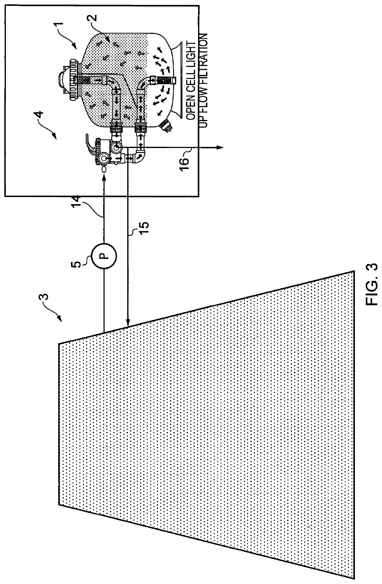
[0134]A mechanical filter apparatus 1 and mechanical filter elements 2 in accordance with aspects of the present invention will now be described with reference to FIGS. 3 to 11. The mechanical filter apparatus 1 is operable in a filtration mode and a backwash mode. When the mechanical filter apparatus 1 is operating in said filtration mode, the mechanical filter elements 2 mechanically filter the liquid by trapping particulates suspended therein. The trapped particulates can subsequently be dislodged to clean the mechanical filter elements 2 when the mechanical filter apparatus 1 operates in said backwash mode. The filtered particulates can be flushed from the mechanical filter apparatus 1 during the backwash mode or during a separate waste (purge) cycle.

[0135]As shown in FIG. 3, the mechanical filter apparatus 1 in the present embodiment is configured to mechanically filter the water in a swimming pool 3. The water in the swimming pool 3 is treated to suppress biological activity, ...


PUM

PropertyMeasurementUnit
lengthaaaaaaaaaa
lengthaaaaaaaaaa
cross-sectional areaaaaaaaaaaa

Abstract

The present disclosure a mechanical filter element (2) for forming a static filter pack (11) to perform mechanical filtration of a liquid. The mechanical filter element (1) has one or more filter cell (19). The present disclosure also relates to a mechanical filter apparatus (1) having a filter chamber (10) containing a plurality of mechanical filter elements (2) for forming the static filter pack (11) to perform mechanical filtration of a liquid. The mechanical filter apparatus (1) is configured to generate a flow of the liquid through the mechanical filter elements (2) during filtration to form the static filter pack (11). Furthermore, the present disclosure relates to a method of mechanically filtering a liquid. A plurality of mechanical filter elements (2) each comprising one or more filter cell (19) are disposed in a filter chamber (10). During filtration, the liquid flows through the filter chamber (10) to establish a static filter pack (11) of said mechanical filter elements (2) to mechanically filter the liquid.

Description

RELATED APPLICATIONS[0001]This application is a 35 U.S.C. § 371 national stage application of PCT Application No. PCT / GB2016 / 000101, filed on May 16, 2016, which claims priority from Great Britain Patent Application No. 1508392.6 filed on May 15, 2015, and Great Britain Patent Application No. 1600483.0 filed on Jan. 11, 2016, the contents of which are incorporated herein by reference in their entireties. The above-referenced PCT International Application was published in the English language as International Publication No. WO 2016 / 185159 on Nov. 24, 2016.TECHNICAL FIELD[0002]The present disclosure relates to a mechanical filter element, to mechanical filter apparatus and to mechanical filtration method(s). More particularly, but not exclusively, the present disclosure relates to mechanical filter elements, mechanical filter apparatus and mechanical filtration methods for filtering water in swimming pools, swimming baths, leisure pools, hot tubs, spas and leisure parks.BACKGROUND[00...

Claims


Application Information

Patent Timeline
Patent Type & Authority Patents(United States)
IPC IPC(8): B01D24/00B01D24/10B01D24/14B01D24/16B01D24/40B01D24/46B01J19/30C02F1/00E04H4/12C02F103/42
CPCB01D24/001B01D23/005B01D23/10B01D24/10B01D24/14B01D24/167B01D24/40B01D24/4636B01D24/4642B01D24/4668B01J19/30C02F1/001E04H4/1209B01D2101/00B01J2219/30223B01J2219/30242B01J2219/30466B01J2219/3188C02F2103/42C02F2303/04C02F2303/16
Inventor JACKSON, NICHOLAS JOHNKUIJPER, JASPER HENDERICUS MARIA
Owner EVOLUTION AQUA LTD
Why Eureka
Try Eureka