High-linearity amplifier

a high-linearity, amplifier technology, applied in differential amplifiers, amplifiers with semiconductor devices/discharge tubes, negative feedback circuit arrangements, etc., can solve problems such as large circuit size of the entire amplifier, serious odd harmonics, and inefficiency in improvemen

Active Publication Date: 2022-07-19
MEDIATEK INC
View PDF30 Cites 0 Cited by
  • Summary
  • Abstract
  • Description
  • Claims
  • Application Information

AI Technical Summary

Benefits of technology

[0007]An amplifier in accordance with an exemplary embodiment of the present invention includes a main operational amplifier, a feedback circuit, and a compensation circuit. The feedback circuit couples an output signal of the main operational amplifier to an input port of the main operational amplifier. The compensation circuit is coupled to the input port of the main operational amplifier to compensate for the non-linearity of the feedback circuit. Specifically, a signal coupled to the input port of the main operational amplifier through the compensation circuit has an inverse phase compared to the output signal of the main operational amplifier.

Problems solved by technology

Due to the velocity saturation effect, the resistance of the feedback resistor Rf is seriously affected (e.g., 2nd-order voltage coefficient in the resistance of the feedback resistor Rf) by a large voltage swing across the feedback resistor Rf, which results in serious odd harmonics (e.g., HD3, HD5, HD7, and so on) in the amplification.
However, the improvement is not efficient.
The circuit size of the entire amplifier is very large.

Method used


Image

  • High-linearity amplifier
  • High-linearity amplifier
  • High-linearity amplifier

Examples


Embodiment Construction

[0021]The following description shows exemplary embodiments carrying out the invention. This description is made for the purpose of illustrating the general principles of the invention and should not be taken in a limiting sense. The scope of the invention is best determined by reference to the appended claims.

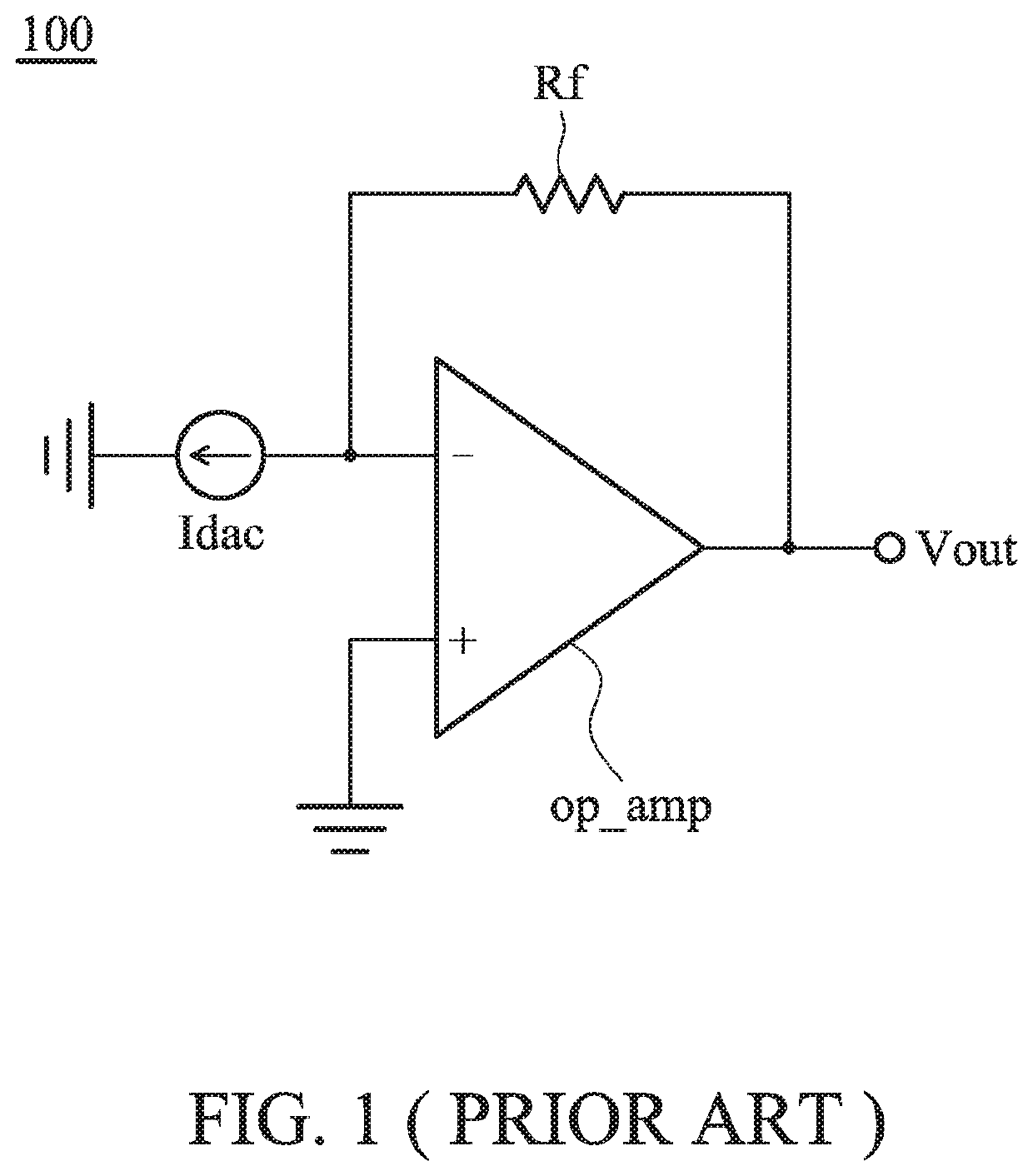
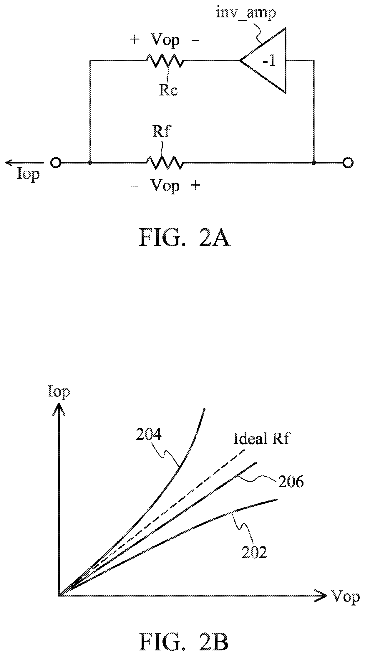
[0022]FIG. 2A and FIG. 2B depict a solution to the non-linearity of the feedback resistor Rf of FIG. 1. An inverse paralleling linearization architecture is introduced.

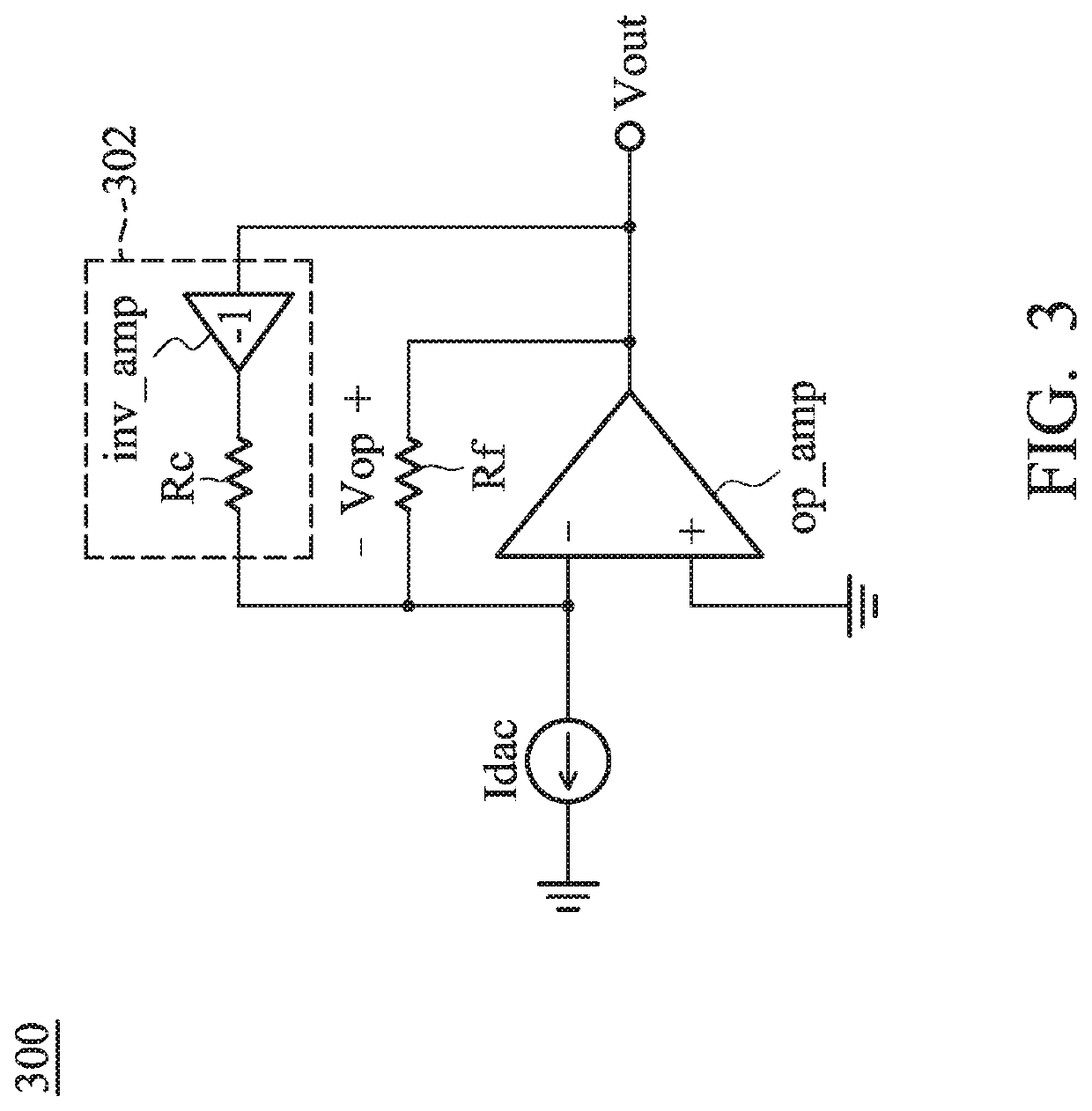
[0023]Referring to FIG. 2A, the voltage Vop across the feedback resistor Rf is inverted by an inverting amplification circuit inv_amp (with an amplitude gain 1) and thereby the voltage across a compensation resistor Rc is in an inverse phase (Vop) compared to the voltage (+Vop) across the feedback resistor Rf. Such architecture is named the inverse paralleling linearization. FIG. 2B shows the current-voltage (I-V) plot of the resistors of FIG. 2B. The I-V plot of the feedback resistor Rf is 202, which contains a...


PUM


Abstract

A high-linearity amplifier including a main operational amplifier, a feedback circuit, and a compensation circuit is shown. The feedback circuit couples an output signal of the main operational amplifier to an input port of the main operational amplifier. The compensation circuit is coupled to the input port of the main operational amplifier to compensate for the non-linearity of the feedback circuit. A signal coupled to the input port of the main operational amplifier through the compensation circuit has an inverse phase compared to the output signal of the main operational amplifier.

Description

CROSS REFERENCE TO RELATED APPLICATIONS[0001]This application claims the benefit of U.S. Provisional Application No. 62 / 937,282, filed on Nov. 19, 2019, the entirety of which is incorporated by reference herein.BACKGROUND OF THE INVENTIONField of the Invention[0002]The present invention relates to operational amplifiers.Description of the Related Art[0003]Operational amplifiers (op amps) are among the most widely used electronic devices today, being used in a vast array of consumer, industrial, and scientific devices. For example, a headphone amplifier may be implemented using an operational amplifier.[0004]FIG. 1 depicts a conventional amplifier 100 implemented by an operational amplifier op_amp. Due to the velocity saturation effect, the resistance of the feedback resistor Rf is seriously affected (e.g., 2nd-order voltage coefficient in the resistance of the feedback resistor Rf) by a large voltage swing across the feedback resistor Rf, which results in serious odd harmonics (e.g....

Claims


Application Information

Patent Timeline
Patent Type & Authority Patents(United States)
IPC IPC(8): H03F1/34H03F1/32
CPCH03F1/34H03F1/3211H03F2203/45601H03F3/45H03F3/45475H03F2203/45528H03F1/083
Inventor WEN, SUNG-HAN
Owner MEDIATEK INC
Why Eureka
Try Eureka