Power amplifier and method for CDMA system

A technology of power amplifier and power amplification, which is applied in the field of CDMA system and can solve problems such as difficult to precisely control power

Inactive Publication Date: 2006-01-11
ERICSSON-LG
View PDF0 Cites 0 Cited by
  • Summary
  • Abstract
  • Description
  • Claims
  • Application Information

AI Technical Summary

Problems solved by technology

Because analog signals are susceptible to noi

Method used


Image

  • Power amplifier and method for CDMA system
  • Power amplifier and method for CDMA system
  • Power amplifier and method for CDMA system

Examples


Embodiment Construction

[0035] In a preferred embodiment, in order to have linearity while removing non-linearity, it is preferable to adjust the voltage level input to the power amplifier, rather than to adjust the amplification control signal of the power amplifier.

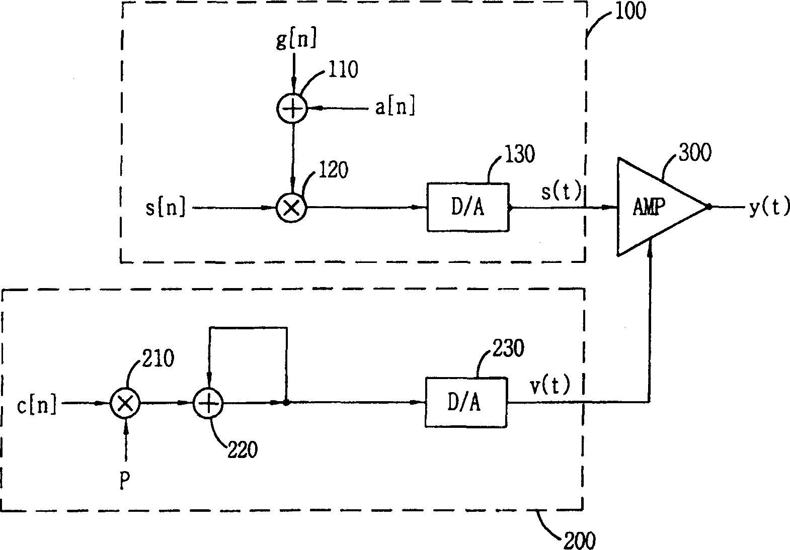
[0036] image 3 It is a schematic block diagram of a power linearization circuit of a CDMA system according to a preferred embodiment of the present invention. Such as image 3 As shown, an adjustment gain (a[n]) is added to the transmission gain signal g[n] to generate linearity in the power amplifier.

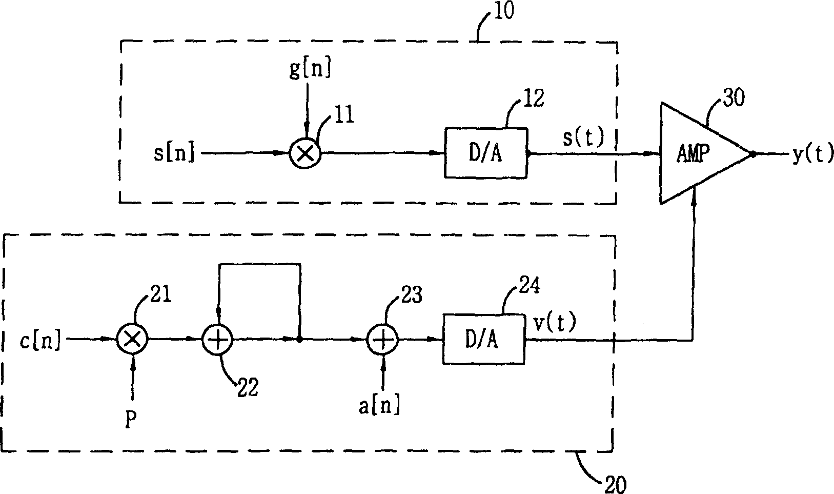
[0037] refer to image 3, the power amplifier preferably includes: a linearization input unit 100, which can eliminate the nonlinearity of the power amplifier 300 by compensating the level of an input signal; an amplification controller 200, which can control the amplification factor of the power amplifier 300; and power Amplifier 300 amplifies the power of the signal s(t) output from the linearization input unit 100 under the con...


PUM


Abstract

A power linearizer of a CDMA system preferably includes a linearization input unit for compensating a level of an input signal to remove a non-linearity of a power amplifier; an amplification controller for controlling an amplification of the power amplifier; and the power amplifier operated under the control of the amplification controller, for amplifying the power of the level-compensated input signal. By adjusting the voltage inputted to the input terminal of the voltage controlled power amplifier (VCA), the non-linearity of the VCA can be accurately compensated and the power compensation can be easily performed. In addition, the capacity of the CDMA system can be increased.

Description

technical field [0001] The invention relates to a CDMA system, in particular to a power amplifier of the CDMA system. Background technique [0002] In general, wireless band amplifiers using active components produce many unwanted distortion components as a function of power level variations. [0003] Especially when the amplifier works near the saturation region, there will be obvious nonlinear phenomena to distort the amplitude and phase of the output signal, and when more than two signals are input, intermodulation will occur between the two input signals Distortion (IMD) components, which have a strong impact on adjacent channels. [0004] The IMD component acts as a noise source, which degrades the transmission quality of the communication system and reduces the capacity of the CDMA system. [0005] figure 1 is a schematic block diagram of a power linearizer for a prior art CDMA system. Such as figure 1 As shown, this power linearization circuit in the prior art in...

Claims


Application Information

Patent Timeline
IPC IPC(8): H04J13/02H04Q7/20H04B7/26H04B7/005H03F1/32
CPCH03F1/3247H03F1/32
Inventor 陈敏镐
Owner ERICSSON-LG
Why Eureka
Try Eureka