
A magnetic levitation molecular pump motor control device with power failure compensation function

A control device and magnetic levitation technology, which is applied in the direction of AC motor control, control system, electrical components, etc., can solve the problems of inability to effectively control the nonlinearity of switching converters and the time-varying characteristics of parameters, and achieve improved integration and versatility, compensation Non-linear and parametric time-varying properties, effects that improve response speed and robustness

Active Publication Date: 2016-01-20
BEIHANG UNIV
View PDF6 Cites 0 Cited by
  • Summary
  • Abstract
  • Description
  • Claims
  • Application Information

AI Technical Summary

Problems solved by technology

[0004] The technical problem of the present invention is to overcome the disadvantage that the switching power supply system used in the power failure compensation of the existing magnetic levitation molecular pump system cannot effectively control the nonlinear and parameter time-varying characteristics of the switching converter, and propose a method based on DSP as the core, based on digital control technology, magnetic levitation permanent magnet motor control device with power failure compensation function

Method used


Image

  • A magnetic levitation molecular pump motor control device with power failure compensation function
  • A magnetic levitation molecular pump motor control device with power failure compensation function
  • A magnetic levitation molecular pump motor control device with power failure compensation function

Examples


Embodiment Construction

[0032] The present invention will be further described below in conjunction with the accompanying drawings and specific embodiments.

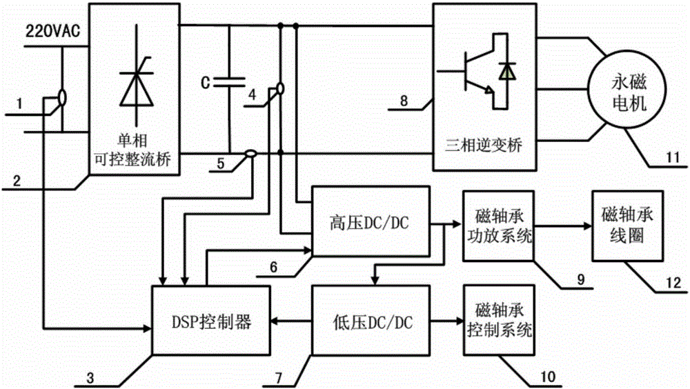
[0033] Such as figure 1As shown, the present invention mainly includes a controllable rectification module 2 , a three-phase inverter module 8 , a DSP control module 3 , a high voltage DC / DC module 6 and a low voltage DC / DC module 7 . When the device is in normal operation, the DSP control module 3 first adjusts the bus voltage to the starting voltage value through the single-phase controllable rectification module 2, then controls the three-phase inverter module 8 to drive the permanent magnet motor to run, and gradually increases the bus voltage to the rated value, The DSP control module 3 outputs 6 channels of PWM signals, using a three-phase six-beat driving method. The PWM adopts the "H_PWM_L_ON" modulation method to control the inverter bridge and drive the motor, and the PWM duty cycle increases from 0 to 50%, and the motor starts Accel...


PUM


Abstract

The invention provides a Maglev (Magnetic Levitation) molecular pump motor control device with an electric power failure compensation function. The Maglev molecular pump motor control device mainly comprises a single-phase controllable rectifier module, a three-phase inverter bridge module, a DSP (Digital Signal Processing) control module, a high-voltage DC (Direct Current) / DC module and a low-voltage DC / DC module. When the Maglev molecular pump motor control device is in normal running, the DSP control module can be used for firstly adjusting busbar voltage into a starting voltage value through the single-phase controllable rectifier module, then controlling the three-phase inverter bridge module to drive a permanent magnetic motor to run and increasing the busbar voltage to a rated value step by step, an external AC (Alternating Current) power supply can be simultaneously monitored through a voltage sensor by a system, the DSP control module controls the high-voltage DC / DC module which serves as a converter to run if external electric power is in failure, the single-phase controllable rectifier module and the three-phase inverter bridge module can be closed, the permanent magnetic motor enters into a power generating mode at the moment, by using a system, energy fed back by the permanent magnetic motor can be converted into a power power supply and a control power supply of a magnetic bearing through the high-voltage DC / DC module and the low-voltage DC-DC module, and the compensation function of the Maglev molecular pump system under the situation that the external electric power is in failure can be realized.

Description

technical field [0001] The invention relates to a magnetic levitation molecular pump motor control device with a power failure compensation function, which can drive a high-speed magnetic levitation permanent magnet motor to realize a soft start function. The fed back energy is converted into the required power type to realize real-time compensation for the magnetic bearing power system and prevent the rotor from falling directly on the rotor during operation. It is especially suitable for the high-speed magnetic levitation molecular pump motor control system that has strict requirements on power supply reliability. Background technique [0002] Molecular pumps are the key core components of high-end scientific instruments and equipment to obtain ultra-high vacuum environments. According to the supporting method of the rotor, molecular pumps are divided into mechanical bearing molecular pumps and magnetic levitation molecular pumps. Compared with the mechanical bearing mole...

Claims


Application Information

Patent Timeline
Patent Type & Authority Patents(China)
IPC IPC(8): H02P23/10H02P27/08
CPCF16C32/0442F16C32/0457
Inventor 刘刚毛琨郑世强韩邦成张樱子孙庆文
Owner BEIHANG UNIV
Learn More