Thermal interface material structures for directing heat in a three-dimensional space

a technology of three-dimensional space and interface material, applied in the field of data processing, can solve the problem that the computer system has evolved into extremely complicated devices

Active Publication Date: 2022-08-16
IBM CORP
View PDF34 Cites 0 Cited by
  • Summary
  • Abstract
  • Description
  • Claims
  • Application Information

AI Technical Summary

Benefits of technology

[0005]Advantages provided by such embodiments for thermal interface material structures for directing heat in a three-dimensional space include providing a thermal interconnect between a heat exchanger and / or a heat spreader plate and components at different elevations relative to a circuit board. Advantages further include providing a thermal interconnect between components with different load requirements. The three-dimensional shape of the TIM sheet allows for accurate TIM placement and retention during manufacturing. The larger surface area provides continuous heat transfer and heat spreading. The three-dimensional TIM sheet is highly compressible, highly conductive at lower loads, and provides a range of gap filling capability for small gaps. Finally, the TIM sheet is easily assembled, easily reworked, and easily replaced. These advantages are achieved by using a single TIM sheet folded to provide a thermal interconnect between at least two planes within a system.
[0019]In an optional embodiment, pressing the upper forming tool to the lower forming tool creates additional folds creating adjacent layers of the TIM sheet adjacent and substantially parallel to the first upper portion, or rolling the first upper portion into a coil. This provides the advantage of additional gap filling for different types of gaps while maintaining a thermal interconnect with the TIM sheet.

Problems solved by technology

Since that time, computer systems have evolved into extremely complicated devices.

Method used


Image

  • Thermal interface material structures for directing heat in a three-dimensional space
  • Thermal interface material structures for directing heat in a three-dimensional space
  • Thermal interface material structures for directing heat in a three-dimensional space

Examples


Embodiment Construction

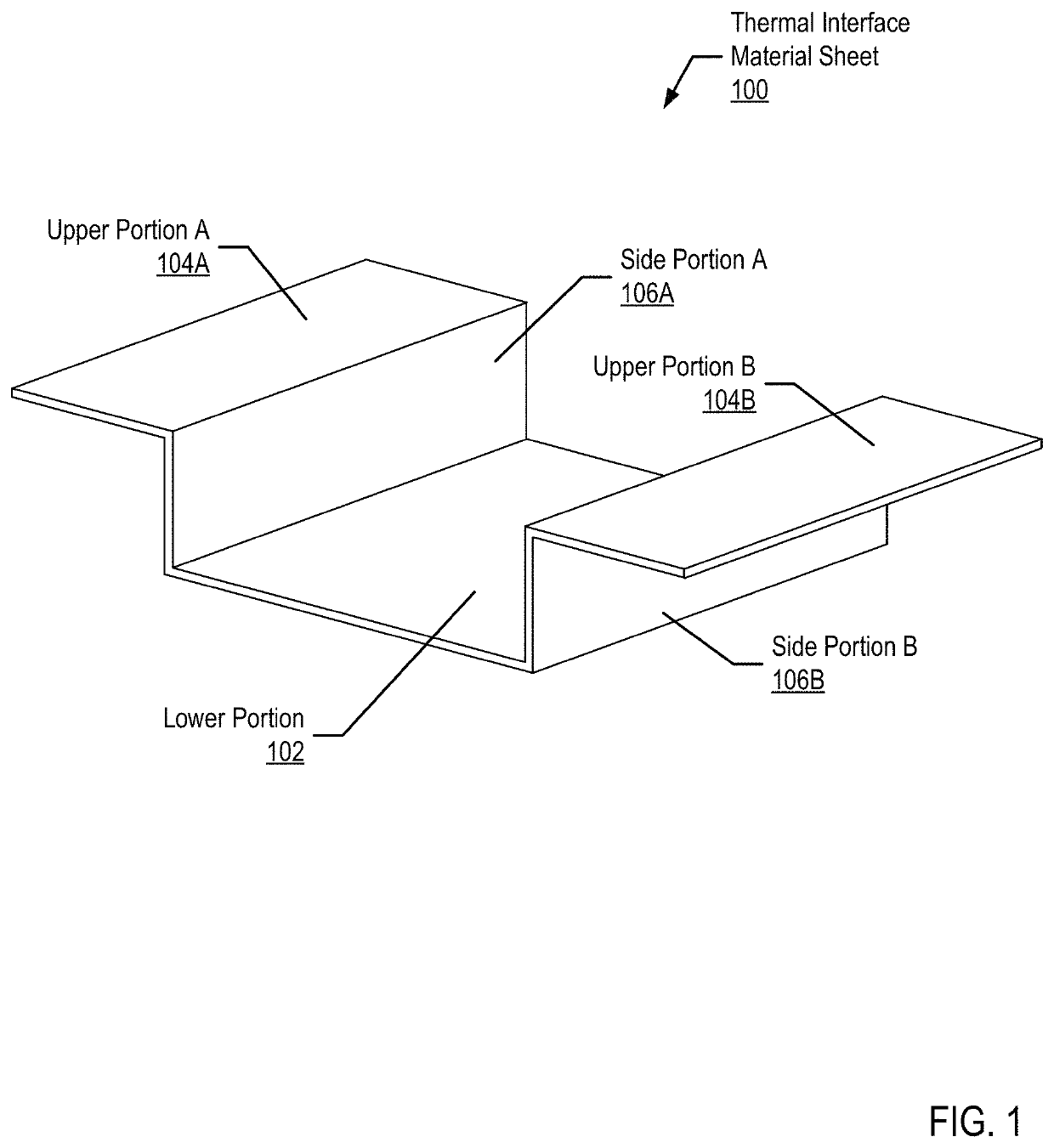
[0029]FIG. 1 sets forth a diagram depicting an example thermal interface material (TIM) sheet for directing heat in a three-dimensional space according to embodiments of the present invention. As shown in FIG. 1, the TIM sheet (100) includes a lower portion (102), two upper portions (upper portion A (104A), upper portion B (104B)), and two side portions (side portion A (106A), side portion B (106B)).

[0030]The TIM sheet (100) is a single, continuous sheet of thermal conducting material. The TIM sheet may be a single material type, such as a graphite TIM sheet. Alternatively, the TIM sheet may be a composite material, such as a particle or fiber filled silicone and / or acrylate TIM sheet. Additionally, the TIM sheet may be a cured or partially cured elastomer matrix, such as silicone, filled with any number of thermally conductive materials. Such thermally conductive materials may include ceramic particles such as, but not limited to, aluminum nitride, boron, nitride, zinc oxide, or al...


PUM


Abstract

A thermal interface material (TIM) structure for directing heat in a three-dimensional space including a TIM sheet. The TIM sheet includes a lower portion along a lower plane; a first side portion along a first side plane; a first upper portion along an upper plane; a first fold between the lower portion and the first side portion positioning the first side portion substantially perpendicular to the lower portion; and a second fold between the first side portion and the first upper portion positioning the first upper portion substantially perpendicular to the first side portion and substantially parallel to the lower portion.

Description

BACKGROUNDField of the Invention[0001]The field of the invention is data processing, or, more specifically, methods and system for thermal interface material structures for directing heat in a three-dimensional space.Description of Related Art[0002]The development of the EDVAC computer system of 1948 is often cited as the beginning of the computer era. Since that time, computer systems have evolved into extremely complicated devices. Today's computers are much more sophisticated than early systems such as the EDVAC. Computer systems typically include a combination of hardware and software components, application programs, operating systems, processors, buses, memory, input / output devices, and so on. As advances in semiconductor processing and computer architecture push the performance of the computer higher and higher, more sophisticated computer software has evolved to take advantage of the higher performance of the hardware, resulting in computer systems today that are much more p...

Claims


Application Information

Patent Timeline
Patent Type & Authority Patents(United States)
IPC IPC(8): H05K7/20G06F1/20
CPCG06F1/20H05K7/20481H01L21/4878H01L23/3737H01L23/373H01L23/433H01L23/473H01L23/4006
Inventor HOFFMEYER, MARK K.MARROQUIN, CHRISTOPHER M.CAMPBELL, ERIC J.CZAPLEWSKI-CAMPBELL, SARAH K.MANN, PHILLIP V.
Owner IBM CORP
Why Eureka
Try Eureka