Fluid-actuated displacement for catheters, continuum manipulators, and other uses

a technology of catheters and actuators, which is applied in the field of catheter actuation, continuum actuation, and other uses, and can solve the problems of collateral tissue trauma, serious pain to patients, and serious damage to patients' health

Active Publication Date: 2022-08-23
PROJECT MORAY INC
View PDF129 Cites 0 Cited by
  • Summary
  • Abstract
  • Description
  • Claims
  • Application Information

AI Technical Summary

Benefits of technology

[0011]The present invention generally provides improved medical devices, systems, and methods, and also provides structures and techniques for improving the behavior of flexible and / or articulated structures such as continuum robotic manipulators, pull-wire catheters, and the like. Catheter-supported therapeutic and diagnostic tools can be introduced into a patient body with a sheath slidably disposed over the tool. Once the tool is aligned with a target tissue, a fluid-driven actuator can move the sheath axially from over the tool, for example, to allow a stent, stent-graft, prosthetic valve, or the like to expand radially within the cardiovascular system, without having to transmit large deployment forces along the catheter shaft and sheath from outside the patient.
[0016]Preferably, a tension member extends axially along the first and second actuators. The tension member can limit distal elongation of the end of the catheter during inflation of the second balloon so that transmission of the inflation fluid distally along the first channel can drive the inflation fluid from the second actuator proximally along the second channel, and so that transmission of the inflation fluid distally along the second channel can drive the inflation fluid from the first actuator proximally along the first channel. Optionally, the tension member elongates axially from a first tension member configuration to a second tension member configuration in response to transmission of the inflation fluid, and the tension member may inhibit elongation beyond the second tension member configuration so as to facilitate driving the sheath back over the receptacle. The tension member may comprise an inner tubular shaft and an outer tubular shaft slidingly receiving the inner shaft therein, with a stop inhibiting telescoping elongation of the shafts beyond the second tension member configuration. The shafts may comprise metal or a rigid polymer, optionally comprising stainless steel. In an advantageous arrangement, the first channel is disposed between the outer tubular shaft and an intermediate tubular shaft, the outer shaft is axially affixed to the tool receptacle, and the second channel is disposed between the inner shaft and the intermediate shaft. The tension member may include corresponding features that axially couple the inner shaft to the outer shaft so as to limit axial sliding.
[0017]The first actuator, the second actuator, or both may comprise an axially segmented balloon having a balloon axis extending along the axis of the catheter body. A first end of the balloon may be axially coupled with the receptacle and a second end axially coupled with the sheath so that inflation pressure against the ends increases an axial length of the balloon and drives the sheath. The segmented balloon can have an outer wall with a plurality of radial members extending radially inwardly from the wall toward a shaft of the catheter body, the shaft extending axially within the balloon. Optionally, the distal portion of the catheter body has a lumen slidably receiving a shaft, a distal end of the shaft being affixed to a distal end of the sheath. A seal can be maintained between the shaft and the catheter body when the sheath moves between the first position and the second position. To improve performance, the second actuator may comprise a balloon having a proximal end and a distal end, and the structure may further comprise a plurality of reinforcing struts extending radially along the proximal balloon end, the distal balloon end, or both so as to facilitate transmission of axial balloon actuation forces between the catheter body and the sheath.
[0019]The systems, devices, and methods described herein may further include one or more of a number of different general features. For example, the tool may comprise an endoluminal implant biased to expand from a small profile configuration to a large profile configuration. The sheath can be configured to radially constrain the implant when the sheath is in the first position, and to slide axially over the implant from the first position toward the second position so as to radially release the implant, optionally within a cardiovascular system of a patient. The tool may optionally comprise a prosthetic valve, often a prosthetic mitral valve. A wide variety of alternative tools may be supportable by the catheter body, with the tool typically being releasably held in the receptacle, although some sheathed tools may be fixed in place. The distal portion of the catheter body may comprise an articulated segment disposed proximally of the receptacle. The distal portion of the catheter body, can, for example, have a plurality of articulated segments configured to position and orient the valve (or other tool) with at least 3 degrees of freedom, with the articulated segment ideally including an articulation balloon array (though other articulation actuators could be used, including pull-wires). Counterintuitively, the second position of the sheath may be distal of the first position so that the sheath moves distally and away from bends of the catheter body disposed between the receptacle and the proximal end when uncovering the tool for use. Regardless, a fluid-driven balloon, bellows, piston, or other actuator can generate significant sheath actuation forces locally (often 3 lb or more, often being 5 or even 10 lb or more, and in some cases being 15 lb or more) sufficiently near where the sheath is to be moved from over the tool so that as to avoid any need for transmitting these forces around bends of the elongate catheter system associated with tortuosity of the vasculature or other body lumen access pathway.
[0020]The sheath actuation devices, systems, and methods described herein may benefit from any of a number of additional technologies and features. Optionally, the first actuator comprises a first balloon. The transmission of the fluid can inflate the first balloon from an uninflated configuration to an inflated configuration. The first balloon in the uninflated configuration can have an uninflated axial length, and the first balloon in the inflated configuration can have an inflated axial length that is greater than the uninflated axial length. Somewhat surprisingly, the first balloon can be distal of the tool and the inflation state of the balloon may help define an overall length of the catheter system. Hence, expansion of the first balloon from the first axial length to the second axial length may extend a distal end of the catheter system distally relative to the receptacle.
[0021]Where, for example, both deployment and retrieval are desired a second actuator may be in fluid communication with a second channel extending along the catheter body, and the second actuator can axially couple the distal portion of the catheter with the sheath so that transmission of inflation fluid along the second channel drives the sheath axially away from the second position and toward the first position. The second actuator may comprise a second balloon, and the transmission of the fluid along the second channel can inflate the second balloon from an uninflated configuration to an elongate inflated configuration. Optionally, the second balloon is distal of the first balloon, and a tension member extends axially along the first and second balloons to limit a total combined length of the two balloons and distal advancement of the end of the catheter during inflation of the second balloon so that axial elongation of the second balloon drives the first balloon and the sheath proximally toward the first position.

Problems solved by technology

Unfortunately, gaining access to and aligning tools with the appropriate internal tissues for evaluation or treatment can represent a significant challenge to the physician, can cause serious pain to the patient, and may (at least in the near term) be seriously detrimental to the patient's health.
Although open surgical techniques have been highly successful, they can impose significant trauma to collateral tissues, with much of that trauma being associated with gaining access to the tissues to be treated.
In fact, some endoluminal techniques that are relatively simple in concept can be very challenging (or even impossible) in practice (depending on the anatomy of a particular patient and the skill of a particular physician).
As the flexible elongate body advances around first one curve and then another, and through a series of branch intersections, the catheter / tissue forces, resilient energy storage (by the tissue and the elongate body), and movement interactions may become more complex and unpredictable, and control over the rotational and axial position of the distal end of a catheter can become more challenging and less precise.
Hence, accurately aligning these elongate flexible devices with the desired luminal pathway and target tissues can be a significant challenge.
Unfortunately, as articulation systems for catheters get more complex, it can be more and more challenging to maintain accurate control over these flexible bodies.
Even after a diagnostic or therapeutic tool is positioned in alignment with a target tissue, it can be difficult to maintain that alignment while deploying or using the tool.
The combination of pulling the sheath proximally while pushing distally against a tool-supporting catheter shaft can make it difficult to maintain tool positioning inside the patient.
These attempts to provide automated catheter control have met with challenges, which may be in-part because of the difficulties in providing accurate control at the distal end of a flexible elongate body using pull-wires extending along bending body lumens.
While the potential improvements to surgical accuracy make all of these efforts alluring, the capital equipment costs and overall burden to the healthcare system of these large, specialized systems is a concern.

Method used


Image

  • Fluid-actuated displacement for catheters, continuum manipulators, and other uses
  • Fluid-actuated displacement for catheters, continuum manipulators, and other uses
  • Fluid-actuated displacement for catheters, continuum manipulators, and other uses

Examples


Embodiment Construction

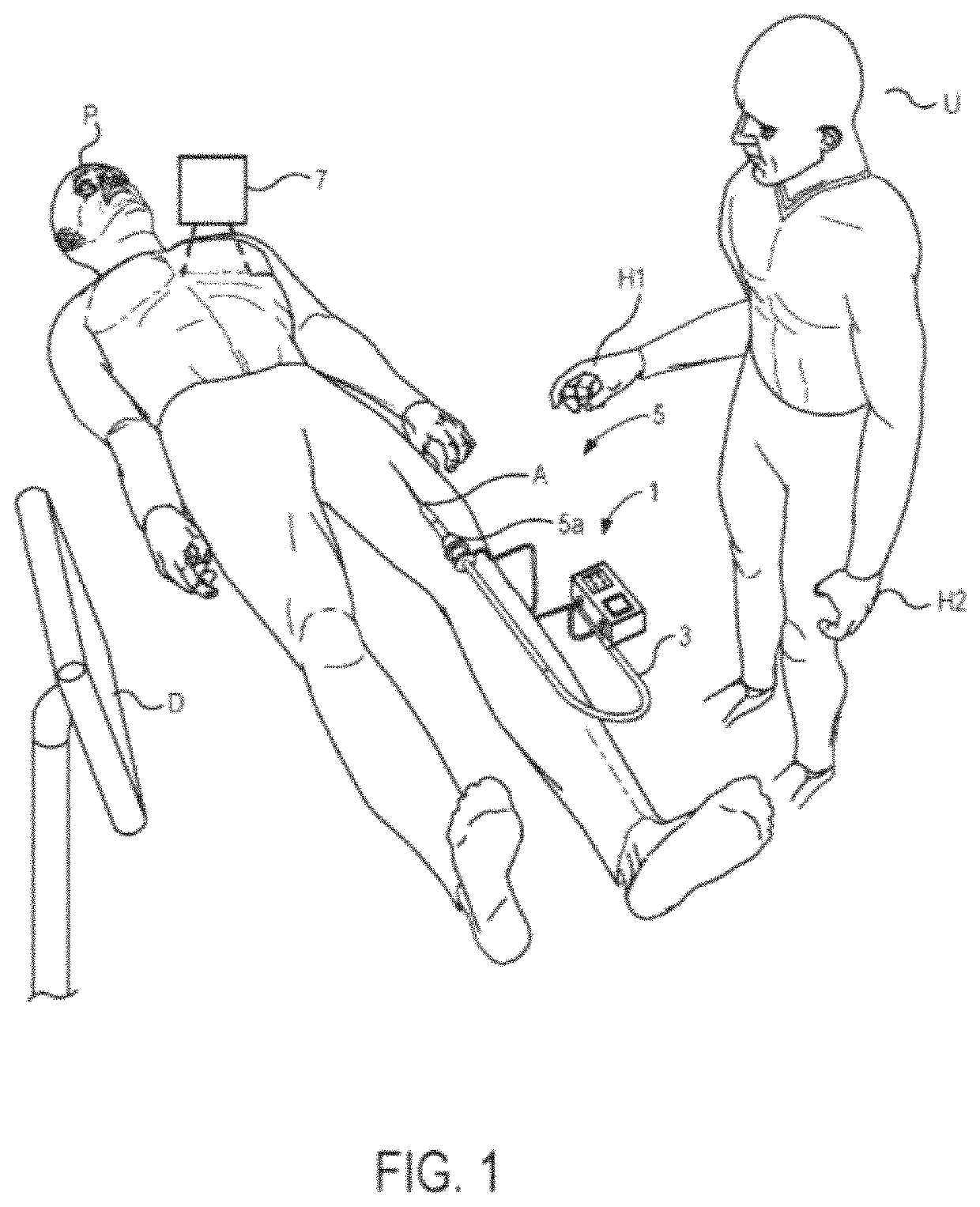
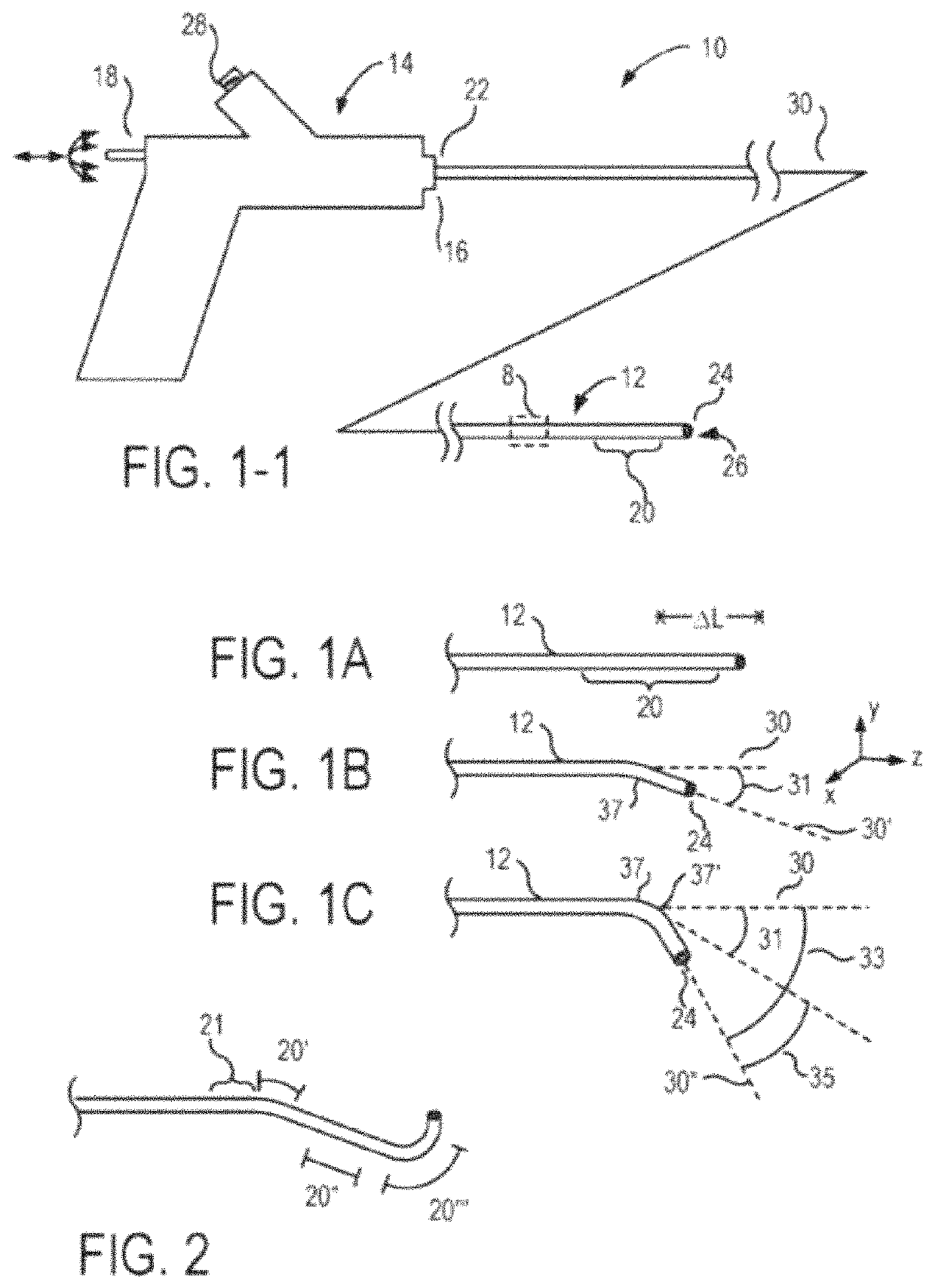
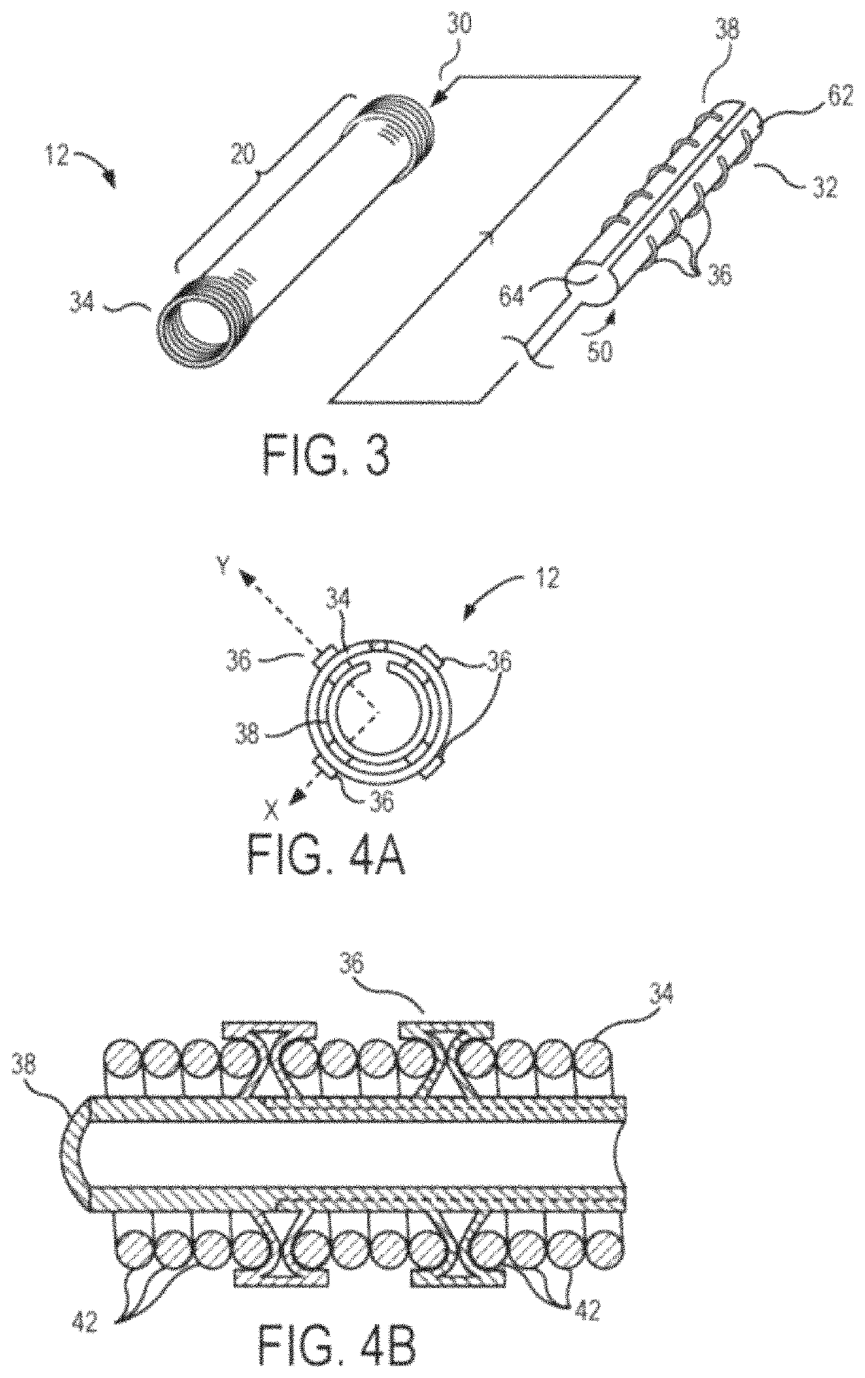
[0048]The present invention generally provides fluid control devices, systems, and methods that are particularly useful for articulating catheters and other elongate flexible structures. In exemplary embodiments the invention provides a modular manifold architecture that includes plate-mounted valves to facilitate fluid communication along a plurality of fluid channels included in one or more multi-lumen shafts, often for articulating actuators of a catheter. Preferred actuators include balloons or other fluid-expandable bodies, and the modular manifold assemblies are particularly well suited for independently controlling a relatively large number of fluid pressures and / or flows. The individual plate modules may include valves that control fluid supplied to a catheter or other device, and / or fluid exhausted from the catheter or other device. A receptacle extending across a stack of such modules can receive a fluid flow interface having a large number of individual fluid coupling por...


PUM


Abstract

Catheter-supported therapeutic and diagnostic tools can be introduced into a patient body with a sheath slidably disposed over the tool. Once the tool is aligned with a target tissue, a first fluid-driven actuator can move the sheath axially from over the tool, for example, to allow a stent, stent-graft, prosthetic valve, or other self-expanding tool, to expand radially within the cardiovascular system, without having to transmit large deployment forces along the catheter shaft and sheath from outside the patient. A second fluid-driven actuator can be arranged in opposition to the first actuator to control release of the expanding tool or to recapture the tool within the sheath. The first and / or second actuators may comprise a balloon having a diameter larger than the sheath to provide the desired deployment and recapture forces with moderate fluid pressure.

Description

CROSS REFERENCE TO RELATED APPLICATIONS[0001]The present application is a continuation of PCT / US2019 / 013942 filed Jan. 17, 2019; which claims the benefit of U.S. Provisional Appln No. 62 / 618,551 filed Jan. 17, 2018; and is a continuation-in-part of U.S. application Ser. No. 15 / 469,085 filed Mar. 24, 2017 (Allowed); which claims the benefit of U.S. Provisional Appln No. 62 / 313,390 filed Mar. 25, 2016; the full disclosures which are incorporated herein by reference in their entirety for all purposes.[0002]The subject matter of the present application is related to that of co-assigned U.S. application Ser. No. 15 / 081,026 entitled “Articulation Systems, Devices, and Methods for Catheters and Other Uses;” Ser. No. 15 / 080,979 entitled “Fluid Drive System for Catheter Articulation and Other Uses;” and Ser. No. 15 / 080,949 entitled “Fluid-Expandable Body Articulation of Catheters and Other Flexible Structures;” all filed on Mar. 25, 2016; the full disclosures which are also incorporated here...

Claims


Application Information

Patent Timeline
Patent Type & Authority Patents(United States)
IPC IPC(8): A61M25/01A61M25/10A61F2/24A61M25/00
CPCA61M25/0155A61F2/2433A61F2/2436A61M25/0122A61M25/10181A61M25/10184A61M2025/0024A61M2025/0058A61M2025/1068
Inventor LABY, KEITH PHILLIPBARRISH, MARK D.
Owner PROJECT MORAY INC
Why Eureka
Try Eureka