Sputtering target and method of producing sputtering target

a technology of sputtering target and target, which is applied in the direction of rolling mill control device, manufacturing tools, work heating devices, etc., can solve the problems of significant reduction of sputtering efficiency and decrease of magnetic flux density on the front surface of the target, and achieve the effect of improving sputtering efficiency

Active Publication Date: 2022-08-23
ULVAC INC
View PDF17 Cites 0 Cited by
  • Summary
  • Abstract
  • Description
  • Claims
  • Application Information

AI Technical Summary

Benefits of technology

[0017]As described above, according to the present invention, it is possible to provide a sputtering target with further improved sputtering efficiency, and a method of producing the sputtering target.

Problems solved by technology

However, in the case where a ferromagnetic material such as cobalt is applied to a sputtering target (hereinafter, target) in a magnetron sputtering method, the following problem occurs.
For example, in the case where the magnetic field leaking from a magnet disposed on the back surface of the target to the front surface of the target is weak, the magnetic flux density on the front surface of the target decrease, and the sputtering efficiency is significantly reduced.

Method used


Image

  • Sputtering target and method of producing sputtering target
  • Sputtering target and method of producing sputtering target
  • Sputtering target and method of producing sputtering target

Examples


example

[0054]FIG. 4 is an X-ray diffraction measurement result of the target according to this embodiment.

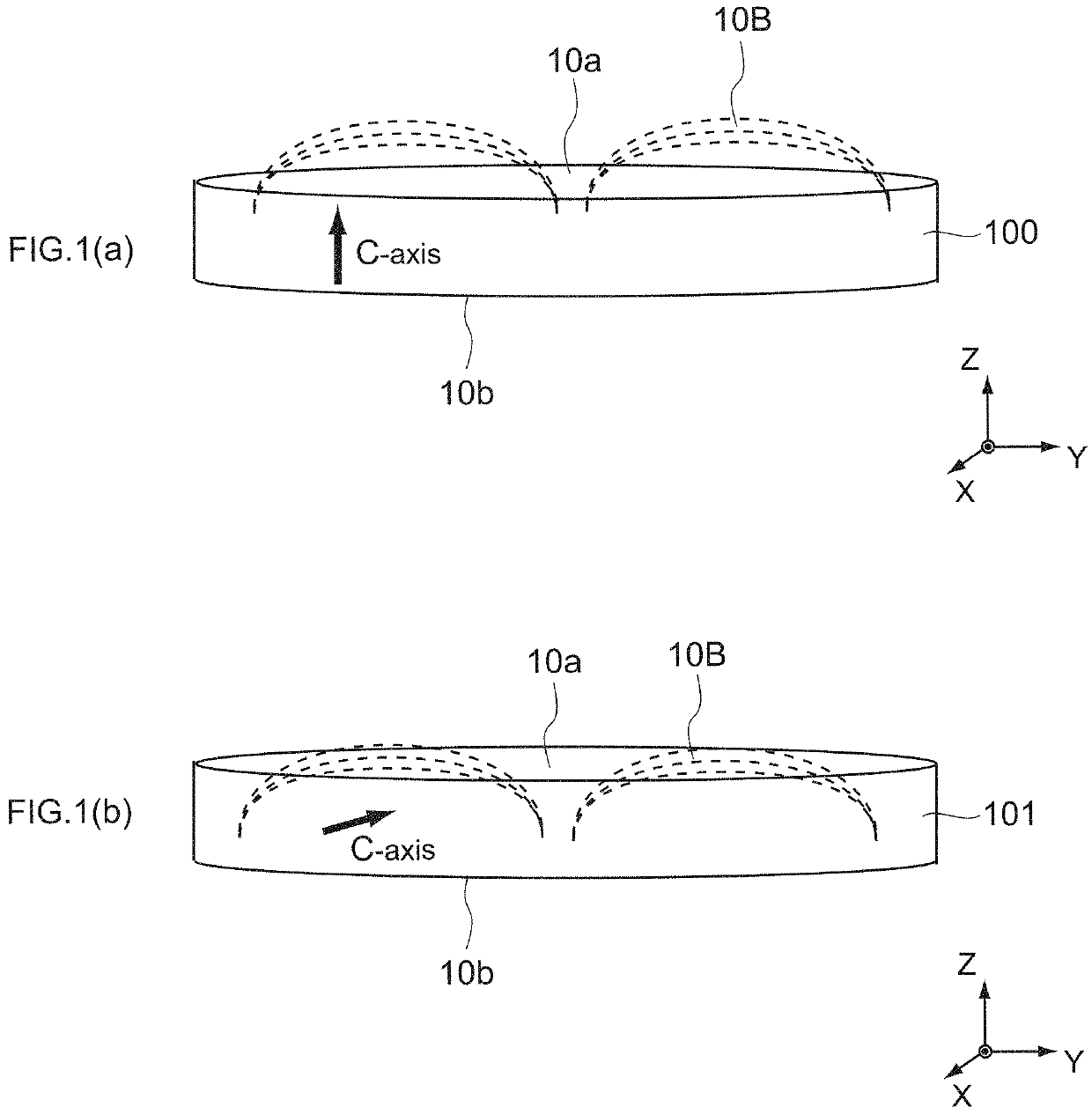
[0055]As the target 100, a disk-shaped one was used. Measurement points are a total of 5 points at the positions of an outer circumference 1, a middle 2, a center 3, a middle 4, and an outer circumference 5 in the sputtering surface 10a. The angle formed by the line connecting the outer circumference 1 and the center 3 and the line connecting the outer circumference 5 and the center 3 is 90°. Further, the thickness of the target 100 is 3 mm and the outer diameter is 400 mm.

[0056]The X-ray diffraction measurement conditions are as follows.

[0057]Scanning method: 2θ / θ method

[0058]Target: Cu

[0059]Tube voltage: 40 kV

[0060]Tube current: 100 mA

[0061]Scan speed: 5° / min

[0062]Sampling width: 0.02°

[0063]Divergent slit: 1°

[0064]Scattering slit: 1°

[0065]Light receiving slit: 0.3 mm

[0066]As shown in FIG. 4, in any place of the target 100, for example, no peak (near 51°) of the fcc (200) plane attrib...


PUM

PropertyMeasurementUnit
sizeaaaaaaaaaa
sizeaaaaaaaaaa
sizeaaaaaaaaaa

Abstract

[Object] To provide a sputtering target with further improved sputtering efficiency, and a method of producing the sputtering target.[Solving Means] In order to achieve the above-mentioned object, a sputtering target according to an embodiment of the present invention is a cobalt target having a sputtering surface and a purity of 99.95 wt % or more. An intensity ratio (I(002)+I(004)) / (I(100)+I(002)+I(101)+I(102)+I(110)+I(103)+I(112)+I(004)) of X-ray diffraction peaks corresponding to a (100) plane, a (002) plane, a (101) plane, a (102) plane, a (110) plane, a (103) plane, a (112) plane, and a (004) plane of a hexagonal close-packed lattice structure along the sputtering surface is 0.85 or more.

Description

CROSS-REFERENCE TO RELATED APPLICATIONS[0001]This application is the U.S. national stage application of International Patent Application No. PCT / JP2019 / 013572, filed Mar. 28, 2019, which claims the benefit under 35 U.S.C. § 119 of Japanese Application No. 2018-140853, filed Jul. 27, 2018, the disclosures of each of which are incorporated herein by reference in their entirety.TECHNICAL FIELD[0002]The present invention relates to a sputtering target and a method of producing the sputtering target.BACKGROUND ART[0003]There is a sputtering method as examples of a method of depositing a thin-film material used for a device such as a semiconductor device. Among them, a magnetron sputtering method with an improved deposition rate is often used.[0004]However, in the case where a ferromagnetic material such as cobalt is applied to a sputtering target (hereinafter, target) in a magnetron sputtering method, the following problem occurs. For example, in the case where the magnetic field leaking...

Claims


Application Information

Patent Timeline
Patent Type & Authority Patents(United States)
IPC IPC(8): C23C14/34C22C19/07C22F1/10H01F41/18
CPCC23C14/3414C22C19/07C22F1/10H01F41/183C22F1/00B21B37/16B21B45/004
Inventor LU, XIAOLINITTA, JUNICHINAKAMURA, AKIRASATOU, MIHO
Owner ULVAC INC
Why Eureka
Try Eureka