Battery and a system for swapping and/or charging a battery of a mobile robot

a mobile robot and battery technology, applied in the field of batteries and a system for swapping and/or charging a mobile robot battery, can solve the problems of battery colliding with the battery holder or acting on the battery holder with at least one force, affecting the physical health of the operator, and affecting the operation of the battery. the vibration of the battery relative to the battery holder is faster, and the damping pin can damp the vibration of the battery faster

Active Publication Date: 2022-08-23
STARSHIP TECH OU
View PDF166 Cites 2 Cited by
  • Summary
  • Abstract
  • Description
  • Claims
  • Application Information

AI Technical Summary

Benefits of technology

[0011]The damping pins can be configured to damp possible vibrations of the battery when the battery is attached to the battery holder. The damping pins can also be configured to distributing possible vibrations across the battery holder when the battery is attached to the battery holder. This can be particularly advantageous when an external or internal factor can cause the battery to vibrate or to move relatively to the battery holder, or can cause the battery holder to vibrate or move relatively to the battery. The damping pin can damp such vibrations, that is, the damping pin can decrease the displacements of the battery relative to the battery holder. The damping pin can preferably stop such vibrations, that is, the damping pin can decrease the displacements of the battery relatively to the battery holder to zero. The damping pins can further be configured to distribute the vibrations of the battery relatively to the battery holder, across the battery holder. That is, the vibrations of the battery relatively to the battery holder, can cause the battery to collide with the battery holder or act on the battery holder with at least one force due to vibrations. Thus, the damping pins can be advantageous as they can distribute such forces due to vibrations across the battery holder on different points of the battery holder. The damping pins can also be advantageous for the battery and preferably for the battery holder, as they can avoid possible damages on the structure of the battery, or the battery holder, due to the vibrations. The damping pins can also be advantageous as they can prevent possible electrical disconnection between the battery and the battery holder due to the vibrations. The battery can be attached to the battery holder, that is, the battery can at least be electrically connected to the battery holder and preferably the battery can be further fixed to the battery holder.
[0094]a) increasing the stability of the battery (400) connected to at least one of the robot battery holder (602) and the station battery holder (600), and

Problems solved by technology

In such cases the operator has to lift the batteries himself Usually such batteries are heavy and may cause damages to the physical health of the operator.
Furthermore, if the operator does not have a charged battery he will have to wait until the battery charges which interrupts the operation of the mobile robot or electric vehicle.
That is, the vibrations of the battery relatively to the battery holder, can cause the battery to collide with the battery holder or act on the battery holder with at least one force due to vibrations.
That is, the damping pins can damp the vibrations of the battery relative to the battery holder faster.
Such inclinations can cause damages on the structure of the battery or the battery holder.
That is, the battery cannot be fixed to the battery holder.
The fixing unit positioned in the open position cannot support the battery.
While traveling, the robots will consume the energy stored in their batteries.
Furthermore, the battery of the mobile robot can be malfunctioning, or its charge-discharge cycles have reached a predefined number, such as the maximum number of charge-discharge cycles that the battery can experience.
That is, the vibrations of the battery relatively to the mobile robot or the battery station, can cause the battery to collide with the mobile robot or the battery station or act on the mobile robot or the battery station with at least one force due to vibrations.
The tolerable misalignment can be the maximum incorrect positioning of the battery relative to the battery station, such that the battery station is able to load and unload the battery.
The tolerable misalignment can also be the maximum incorrect positioning of the battery station relative to the battery, such that the battery station is able to load and unload the battery.

Method used


Image

  • Battery and a system for swapping and/or charging a battery of a mobile robot
  • Battery and a system for swapping and/or charging a battery of a mobile robot
  • Battery and a system for swapping and/or charging a battery of a mobile robot

Examples


Embodiment Construction

[0161]In this section, exemplary embodiments of the battery station 10 will be described, referring to the figures. These examples are given to only provide further understanding of the invention and do not intend to limit the scope of the present teaching in any way.

[0162]In the following description, a series of features and / or steps are described. The skilled person will appreciate that unless required by the context, the order of features and steps is not critical for the resulting configuration and its effect. Further, it will be apparent to the skilled person that irrespective of the order of features and steps, time delays between steps can be present between some or all of the described steps.

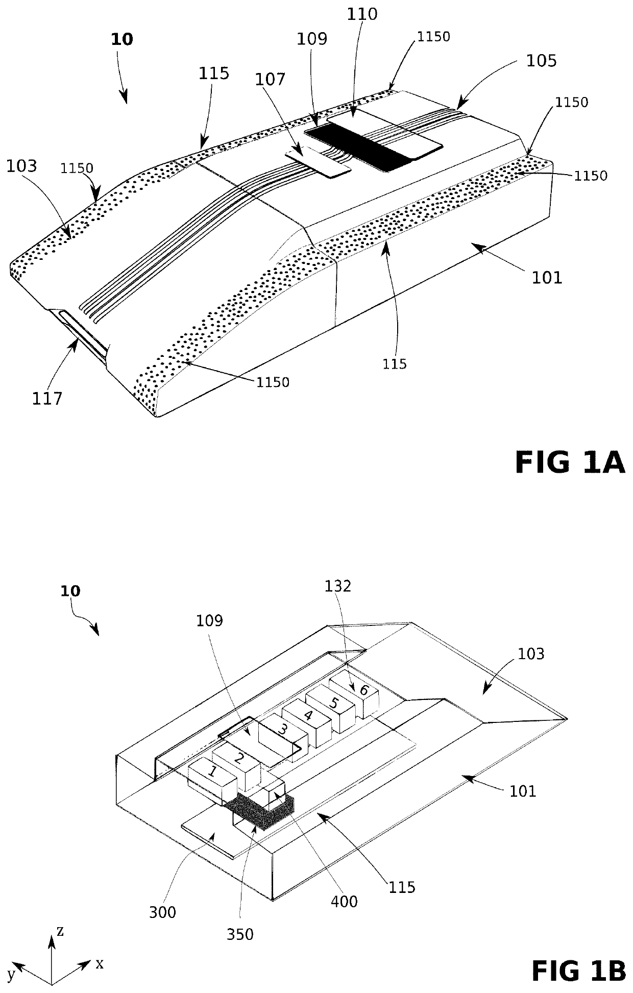
[0163]FIG. 1A depicts an outer perspective view of an embodiment of the battery station 10. Throughout the text, to keep the sentences clear and not overloaded, the battery station 10 may be referred to as station 10. The embodiment of the station 10 as depicted in FIG. 1A, may comprise...


PUM

PropertyMeasurementUnit
heightaaaaaaaaaa
heightaaaaaaaaaa
heightaaaaaaaaaa

Abstract

A battery configured to be attached to a battery holder for use by a mobile robot comprising: a battery body encapsulating the battery; at least two electrical connectors protruding from the battery body; at least one fixing unit located on the battery body said fixing unit configured to fix the battery to the battery holder; at least two damping pins protruding from the battery body; and at least one battery communication component configured to transmit battery status data. A battery holder configured to hold the battery and at least one of storing, swapping and charging a battery.

Description

RELATED APPLICATIONS[0001]This application is a continuation of PCT / EP2018 / 063615, filed May 24, 2018 and claims priority from European application no. 17173111.0, filed May 26, 2017, the entire contents of both of which are hereby fully incorporated herein by reference for all purposes.FIELD[0002]The invention relates to the field of swapping and charging a battery of a mobile robot. More particularly the present invention relates a mobile robot battery that can be swapped and charged by a battery station.INTRODUCTION[0003]As technology improves mobile robots are becoming part of people's everyday life. More and more tasks are being automated and accomplished by mobile robots. Further the need for a safer environment is driving the automotive industry into increasing the production of electric vehicles. Thus, the number of mobile robots and electric vehicles is increasing more and more. In order to operate, usually, these mobile robots and electric vehicles require electric energy,...

Claims


Application Information

Patent Timeline
Patent Type & Authority Patents(United States)
IPC IPC(8): H02J7/00H01M10/44B60L50/64B60L53/66B60L53/80H01M10/42H01M50/20B60L53/35H01M50/204H01M50/262
CPCH01M10/44B60L50/64B60L53/35B60L53/66B60L53/80H01M10/425H01M50/20H02J7/0013B60L2200/40H01M2010/4278H01M2220/20B60L53/36B60L53/37B60L50/66Y02P90/60Y02T90/16Y02T10/70Y02T10/7072Y02T90/12Y02E60/10H01M50/204H01M50/262
Inventor VÄIN, LAURIVALDEK, VILJARLIIVIK, MÄRTLEND, HENRIKHARAGORGIIEV, SERGIIJÄRVE, MARKUSHERRANEN, HENRIKHEINLA, AHTIEVARD, VEIGOBIENE, TOMMY
Owner STARSHIP TECH OU
Why Eureka
Try Eureka