Terminal electrical connector and electrical connector assembly comprising thereof

Active Publication Date: 2022-08-23
KUNSHAN OUTDOOR SOLUTIONS ELECTRONICS CO LTD
View PDF6 Cites 0 Cited by
  • Summary
  • Abstract
  • Description
  • Claims
  • Application Information

AI Technical Summary

Benefits of technology

The present invention provides a terminal electrical connector that can be easily detached and assembled quickly. The connector has high strength in the connection and is convenient and reliable. In terms of secondary effects, the connector is easier to assemble than conventional connectors, improving manufacturing efficiency and reducing costs.

Problems solved by technology

Since product reliability may affect the operation of the overall equipment, the requirements for reliability of electrical connectors are of course high.

Method used


Image

  • Terminal electrical connector and electrical connector assembly comprising thereof
  • Terminal electrical connector and electrical connector assembly comprising thereof
  • Terminal electrical connector and electrical connector assembly comprising thereof

Examples


first embodiment

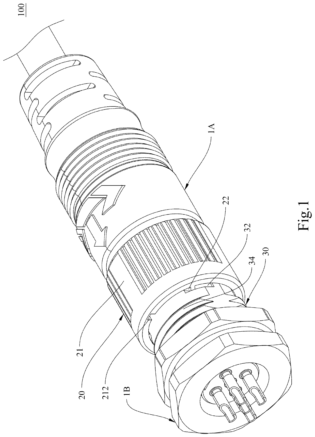
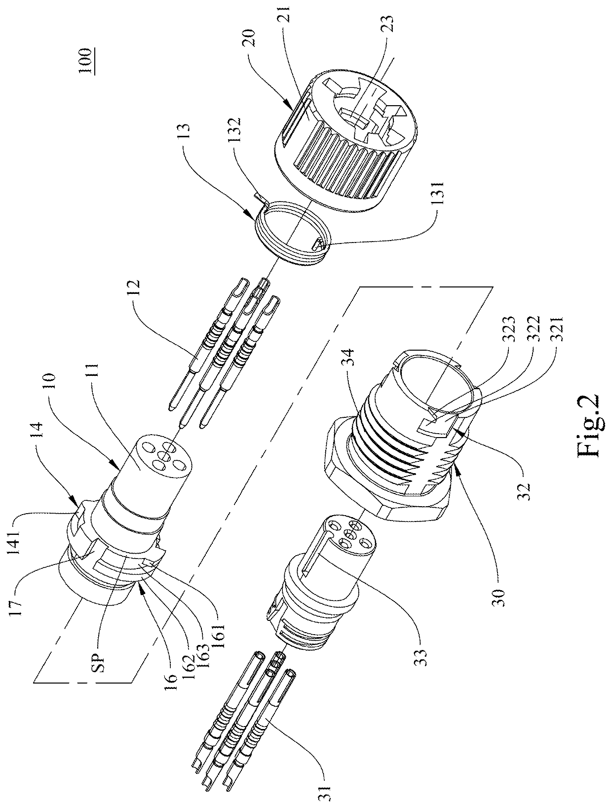
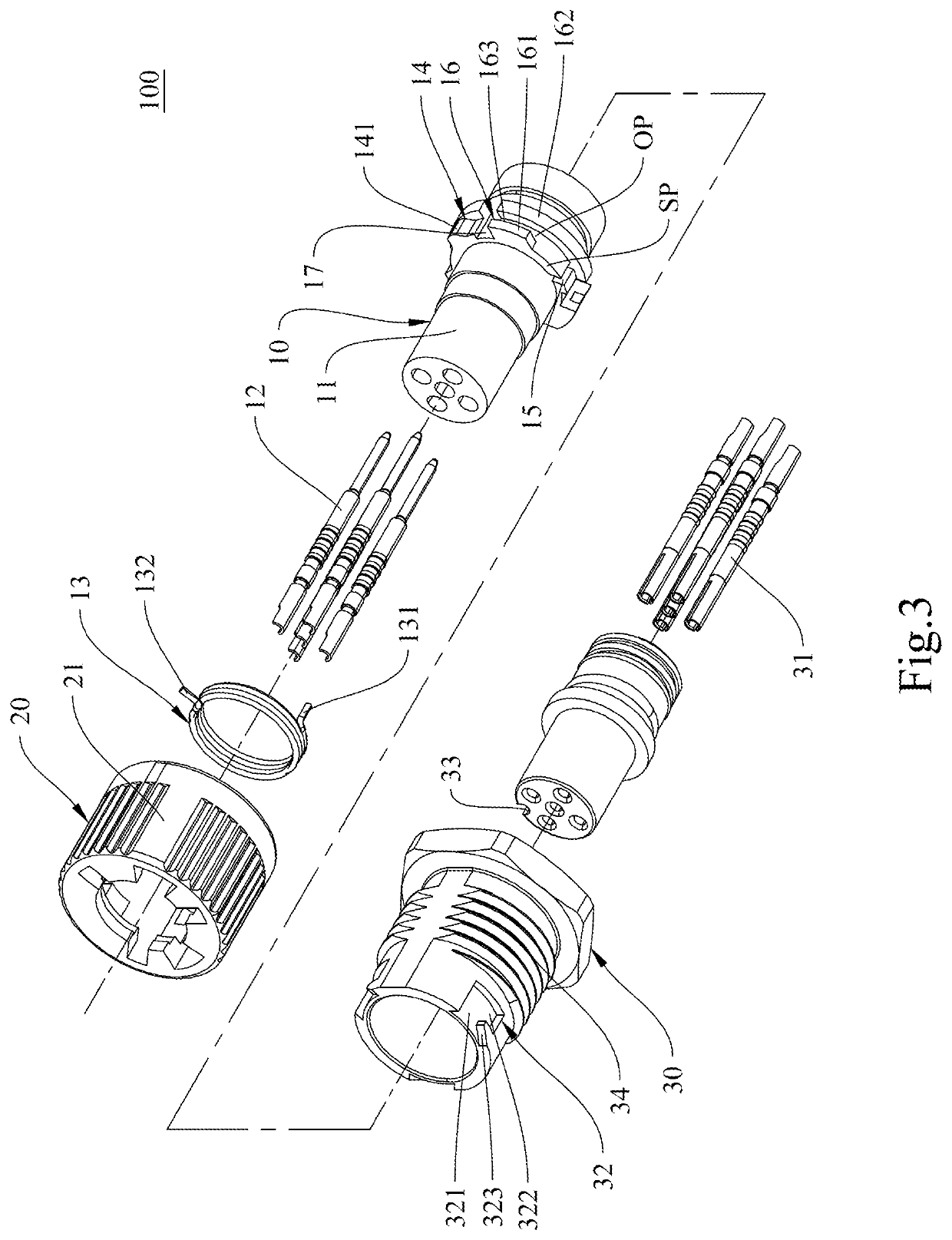
[0032]The specific structure of the electrical connector assembly 100 of the present invention has been described in detail above. The following describes the use state of the electrical connector assembly 100 of the invention. Please refer to FIG. 5 and FIG. 6 respectively for a schematic diagram (1) of the combination of male and female terminals and a schematic diagram (2) of the combination of male and female terminals of the invention.

[0033]First, as shown in FIG. 5, during the assembling stage of the male and female terminals, the first limiting portion 112 (e.g., a fool-proof rib) of the first terminal unit body 11 is aligned with the second limiting portion 33 (e.g., a fool-proof groove) of the second terminal unit body 30 (as shown in FIG. 2 and FIG. 7) to combine the first terminal unit body 11 and the second terminal unit body 30 in the axial direction. The rotating cap 20 is configured such that when the first limiting portion 112 is aligned to the second limiting portio...

second embodiment

[0042]Except for the above-mentioned embodiments, the present invention can also be implemented with the same structure when the male and female terminals are swapped. Please refer to FIG. 13 and FIG. 14, which are schematic diagrams (1) and (2) of the appearance of the invention.

[0043]In the second embodiment of the present invention, the first terminal electrical connector 1C can be implemented in the form of a male terminal, and the second terminal electrical connector 1D can be implemented in the form of a female terminal in cooperation with the first terminal electrical connector 1C. Specifically, the first terminal electrical connector 1C includes a rotating cap 20A and a first terminal unit 10A provided in conjunction with the rotating cap 20A, wherein the internal structure of the rotating cap 20A is basically the same as that of the first embodiment, and will not be repeated. Compared with the first embodiment, the electrical terminal 12A on the first terminal unit body 11A...


PUM


Abstract

The present invention provides a terminal electrical connector, which includes a terminal unit and a rotating cap. The terminal unit includes a terminal unit body, one or a plurality of electrical terminals provided inside the terminal unit body, and a torsion spring positioned on the terminal unit body. A limiting groove for limiting a pivotal stroke and a first positioning groove for positioning a first end of the torsion spring are provided on an outer peripheral side of the terminal unit body. The rotating cap includes a cap body, and one or a plurality of locking blocks provided on the cap body for locking on another terminal electrical connector. A sliding block and a second positioning groove are provided on an inner circumference of the cap body. The sliding block is used for limiting the pivotal stroke of the rotating cap relative to the terminal unit body, and the torsion spring is used for inertially returning the rotating cap to a position of a reset angle relative to the terminal unit body.

Description

BACKGROUND OF THE INVENTION1. Technical Field[0001]The present invention relates to a terminal electrical connector and an electrical connector assembly comprising thereof, and more particularly to a quick-disassembly and quick-assembly terminal electrical connector and an electrical connector assembly comprising thereof.2. Description of Related Art[0002]An electrical connector is a conductive device that connects electrical circuits. These components can be used as end points for connections between different components in the same circuit system, or used to provide power and data connections between different circuit systems and devices. Electrical connectors are widely used in various electrical circuits to provide the function of connecting or disconnecting circuits. The electrical connector is called a pair of male and female because of its form. In the common form, the mobile end is mostly male and the fixed end is mostly female. Sometimes it is determined by the appearance o...

Claims


Application Information

Patent Timeline
IPC IPC(8): H01R13/625H01R13/631
CPCH01R13/625H01R13/631H01R2107/00
Inventor HUANG, DE YAOHUNG, TENG SHENGHUNG, JUI CHIHHSUEH, FENG CHING
Owner KUNSHAN OUTDOOR SOLUTIONS ELECTRONICS CO LTD
Why Eureka
Try Eureka