System for the reversible transformation of a reciprocating motion in a rotary motion

a technology of reciprocating motion and rotary motion, which is applied in the direction of reciprocating piston engines, positive displacement engines, combustion engines, etc., can solve the problems of reducing but not solving, reducing the pressure of the combustion gas in the piston in the cylinder, and being relatively inefficien

Active Publication Date: 2022-10-11
IBS MOTORTECH ITAL SRL
View PDF43 Cites 0 Cited by
  • Summary
  • Abstract
  • Description
  • Claims
  • Application Information

AI Technical Summary

Benefits of technology

[0021]According to another advantageous aspect of the present invention, it is possible to make the surface of the rotor profile in different ways. As a matter of, according to the state of the art document U.S. Pat. No. 7,942,115, the contact surface with the cursor is always a flat surface on which the force generated by the cursor acts perpendicularly. According to the present invention the contact plane of the slider / follower it is inclined and in such a way that different angles of inclination of the slider / follower can be provided, obtaining a greater efficiency, and thus obtaining a number of possible constructive configurations.
[0023]According to another advantageous aspect of the present invention, it is possible to provide different embodiments of the system, wherein each of them has a determined arrangement of the actuating devices with respect to the rotor surface. More precisely, by varying the angle of inclination of the actuating devices with respect to the normal direction of the rotor surface it is possible to increase or decrease the value of the force exerted by the actuating devices on the spiral profile, and consequently increase or decrease the torque value of the rotor, while maintaining the cycle phases unchanged.
[0024]According to another advantageous aspect of the present invention, it is possible to manage the inclination of the actuating device(s) and, therefore, the direction of the force applied to the rotor, thus obtaining the possibility of varying the stroke of the urging member in a complete revolution of the rotor.

Problems solved by technology

This solution of the prior art has proved satisfactory, although it has the disadvantage of that the thrust of the piston in the cylinder is based solely on the pressure of the combustion gas.
This is a realization that decreases but does not solve the problems of environmental pollution, and is also relatively inefficient.

Method used


Image

  • System for the reversible transformation of a reciprocating motion in a rotary motion
  • System for the reversible transformation of a reciprocating motion in a rotary motion
  • System for the reversible transformation of a reciprocating motion in a rotary motion

Examples


first embodiment

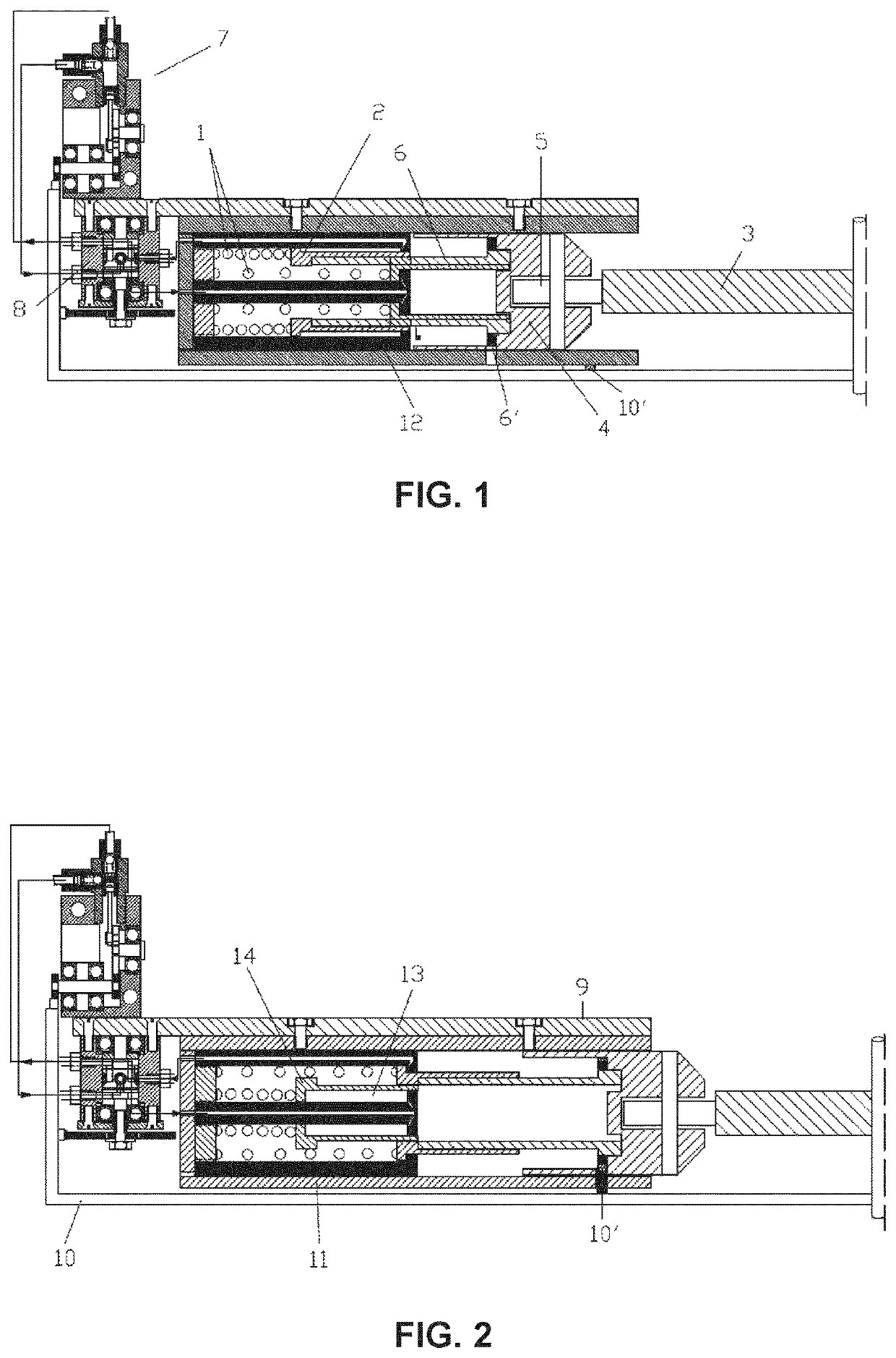
[0026]FIG. 1 is a schematic cross-sectional view of an actuating cylinder according to the present invention, and wherein a first operating condition of the same it is shown;

[0027]FIG. 2 it is a schematic cross-sectional view of the cylinder of FIG. 1 in a second operating condition thereof;

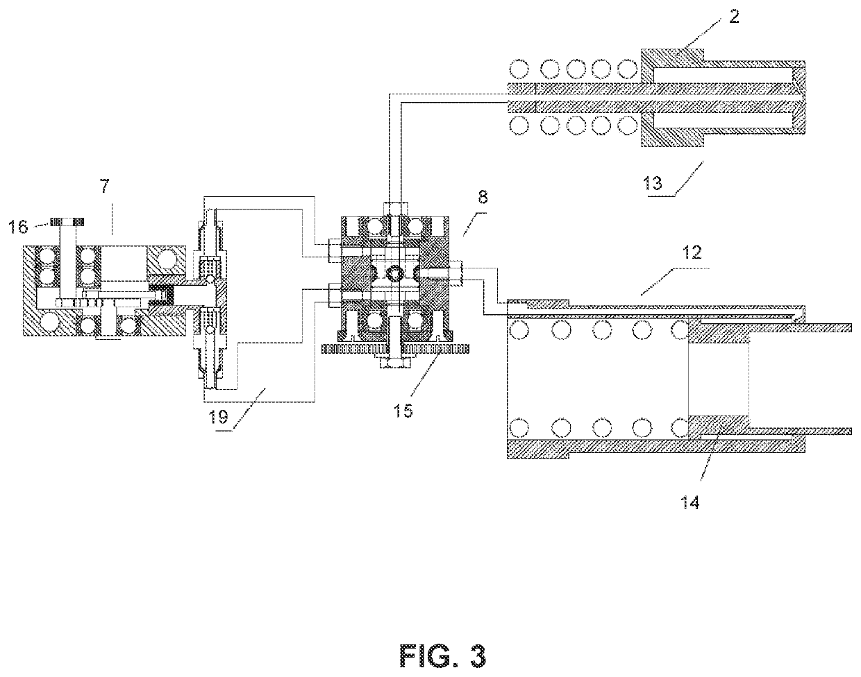
[0028]FIG. 3 it is a schematic sectional view illustrating in part and in detail some components of the hydraulic supply system of the actuating device of FIGS. 1 and 2 according to the invention;

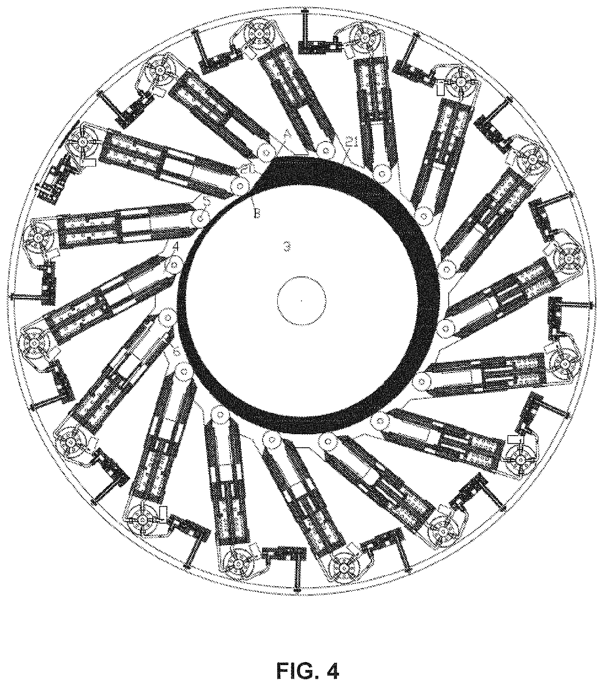
[0029]FIG. 4 it is a schematic and sectional view illustrating the system consisting of a plurality of actuating devices according to the preceding figures and associated with a rotor having a spiral profile according to the invention;

second embodiment

[0030]FIGS. 5A and 5B are schematic and cross-sectional views of two operating conditions of the system of the present invention and thereof, and wherein internal combustion cylinders are provided as actuating devices associated with a spiral profiled rotor;

third embodiment

[0031]FIG. 6 it is a schematic view of the system of the present invention, wherein actuating devices acting both on the outer profile and on the inner profile of the spiral rotor;


PUM


Abstract

The present invention provides a system for the reversible transformation of a reciprocating motion in a rotary motion, which comprises one or more actuating devices (11) adapted to cooperate on at least one interaction surface of a spiral profiled rotor (3), the system it is characterized in that each actuating device of said plurality of actuating devices (11) comprises hydraulic or internal combustion cylinders; the arrangement being such that each actuating device (11) urges a tubular slidable rod coupled to a respective cylinder, said tubular rod being associated with a slider (5), the slider (5) being adapted to transmit the thrust of said tubular rod (6) on said at least one interaction surface of the spiral profiled rotor (3) creating a torque on said rotor (3).

Description

[0001]The present invention relates to a system for the reversible transformation of a reciprocating motion in a rotary motion and, more precisely, to a system for the reversible transformation of a reciprocating motion in a rotary motion which incorporates a spiral rotor.STATE OF THE ART[0002]An internal combustion engine is known from U.S. Pat. No. 7,942,115 which describes a system for converting a reciprocating rectilinear motion into a rotational motion. The system comprises an assembly of internal combustion cylinders, each of which has a rod which pushes a slider over the surface of a rotor. The rotor has a cross section with a spiral profile, and in such a way that the slider follows the surface and performs a compression and an expansion step. This solution of the prior art has proved satisfactory, although it has the disadvantage of that the thrust of the piston in the cylinder is based solely on the pressure of the combustion gas. This is a realization that decreases but ...

Claims


Application Information

Patent Timeline
Patent Type & Authority Patents(United States)
IPC IPC(8): F01B1/06F01B9/06F02B57/08F02B75/22F02B75/26F02B75/18
CPCF01B1/0624F01B9/06F01B2009/061F02B57/08F02B75/222F02B75/265F02B2075/1864F01B1/062
Inventor SKULIC, IVAN
Owner IBS MOTORTECH ITAL SRL
Why Eureka
Try Eureka