Power converter

a converter and current sensor technology, applied in the direction of dc-ac conversion without reversal, electrical apparatus construction details, electrochemical generators, etc., can solve the problems of reducing the particularly high temperature of reactors, etc., to reduce heat and leakage flux, restrain magnetic fluxes, and reduce the effect of measuring accuracy of current values measured by current sensors

Active Publication Date: 2022-10-11
DENSO CORP
View PDF3 Cites 0 Cited by
  • Summary
  • Abstract
  • Description
  • Claims
  • Application Information

AI Technical Summary

Benefits of technology

[0005]The present disclosure is accomplished in view of the above problems, and an object of the present disclosure is to reduce the influence of heat and a leakage flux from a reactor on a current sensor in a power converter to be provided in a fuel cell unit.
[0006]A power converter according to the present disclosure is a power converter to be provided in a fuel cell unit and includes a reactor, a power module, a bus bar, a current sensor, and a partition. The power module is placed side by side with the reactor along a mounting surface of the power converter. An output terminal of the reactor is connected to an input terminal of the power module via the bus bar. The current sensor is provided on the bus bar. The partition is made of metal having a magnetic shielding effect, the partition being configured to separate the reactor from the current sensor. The partition is made of metal having a magnetic shielding effect, so that the partition reduces the influence of radiant heat from the reactor on the current sensor and also reduces the influence of leakage fluxes on the current sensor.
[0007]In the power converter according to the present disclosure, the output terminal of the reactor is provided on either one of a surface of the reactor on a first side and a surface of the reactor on a second side, the first side being a side farther from the mounting surface across a plane passing through a center of the reactor and parallel to the mounting surface, the second side being a side closer to the mounting surface from the plane. On a side opposite to a side where the output terminal of the reactor is provided out of the first side and the second side, the bus bar extends to pass through the partition from a space where the reactor is placed to a space where the current sensor is placed. Since such a positional relationship is provided between the position of the output terminal of the reactor and the position where the bus bar passes through the partition, a long bus bar length is secured from the reactor to the current sensor, and heat transfer from the reactor to the current sensor via the bus bar is reduced.
[0010]In the power converter according to the present disclosure, a part of the bus bar at least from the partition to the input terminal of the power module may be formed straight. Magnetic fluxes corresponding to the magnitude of a current are generated around the bus bar. In a case where a part of the bus bar from the partition to the input terminal of the power module is formed straight, the magnetic fluxes are unidirectional, so that magnetic fluxes in various directions are restrained from acting on a part where the current sensor is provided. That is, a decrease in measuring accuracy of a current value measured by the current sensor is restrained. The bus bar may be bent in a part from the output terminal of the reactor to the partition. In order to connect the output terminal of the reactor to the input terminal of the power module, it is necessary that the bus bar be bent once or several times. When the bus bar is bent on a side opposite to the current sensor across the partition, it is possible to restrain magnetic fluxes generated in other parts and having different directions from acting on the part where the current sensor is provided.
[0011]In the power converter according to the present disclosure, a plurality of reactors may be provided in line on the mounting surface. In this case, respective bus bars are provided for the reactors, so that the reactors provided in line are connected to a single power module in parallel via the respective bus bars. Respective current sensors are provided for the bus bars. The partition may be provided along the line of the reactors. As to one current sensor, the partition reduces heat and leakage fluxes from a reactor corresponding to the current sensor and also reduces the influence of heat and leakage fluxes from other reactors.
[0012]As has been described above, with the power converter of the present disclosure, the partition made of metal and separating the reactor from the current sensor reduces the influence of radiant heat from the reactor on the current sensor and also reduces the influence of leakage fluxes on the current sensor. Further, a long bus bar length is secured from the reactor to the current sensor, and heat transfer from the reactor to the current sensor via the bus bar is reduced.

Problems solved by technology

Due to heat generation by core loss in addition to heat generation by conduction loss of coils, the temperature of the reactors particularly easily becomes high among component parts provided in the power converters.
Further, magnetic fluxes leaking out from the reactors reduce the measuring accuracy of current values measured by the current sensors.

Method used


Image

  • Power converter
  • Power converter
  • Power converter

Examples


first embodiment

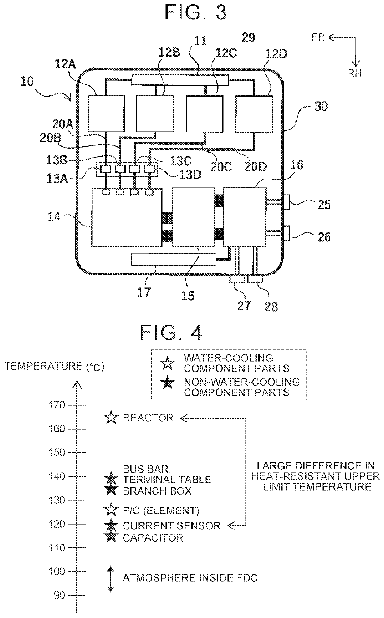
[0050]A reactor cooler 18 configured to cool the reactor 12 is provided between the reactor 12 and the bottom portion 31b of the partition 31. That is, a surface of the reactor 12 on the lower side is cooled by the reactor cooler 18. When a side farther from the mounting surface 50 across a plane 51 passing through the center of the reactor 12 and parallel to the mounting surface 50 is taken as a first side, and a side closer to the mounting surface 50 from the plane 51 is taken as a second side, the surface of the reactor 12 on the lower side is a second-side surface, and a surface of the reactor 12 on the upper side is a first-side surface. In the first embodiment, an output terminal 12a of the reactor 12 is provided on the surface of the reactor 12 on the upper side as the first-side surface.

[0051]The partition 31 has a hole 32 through which the bus bar 20 is passed. A position where the hole 32 is provided is a part of the bottom portion 31b, the part being close to the wall por...

second embodiment

[0061]In the second embodiment, the IPM substrate 19 integrated with the ECU is put on the low ceiling 33b. The IPM substrate 19 is connected to the IPM 14 across the low ceiling 33b. The upper cover 40 covering the upper side of the IPM substrate 19 is attached onto the low ceiling 33b.

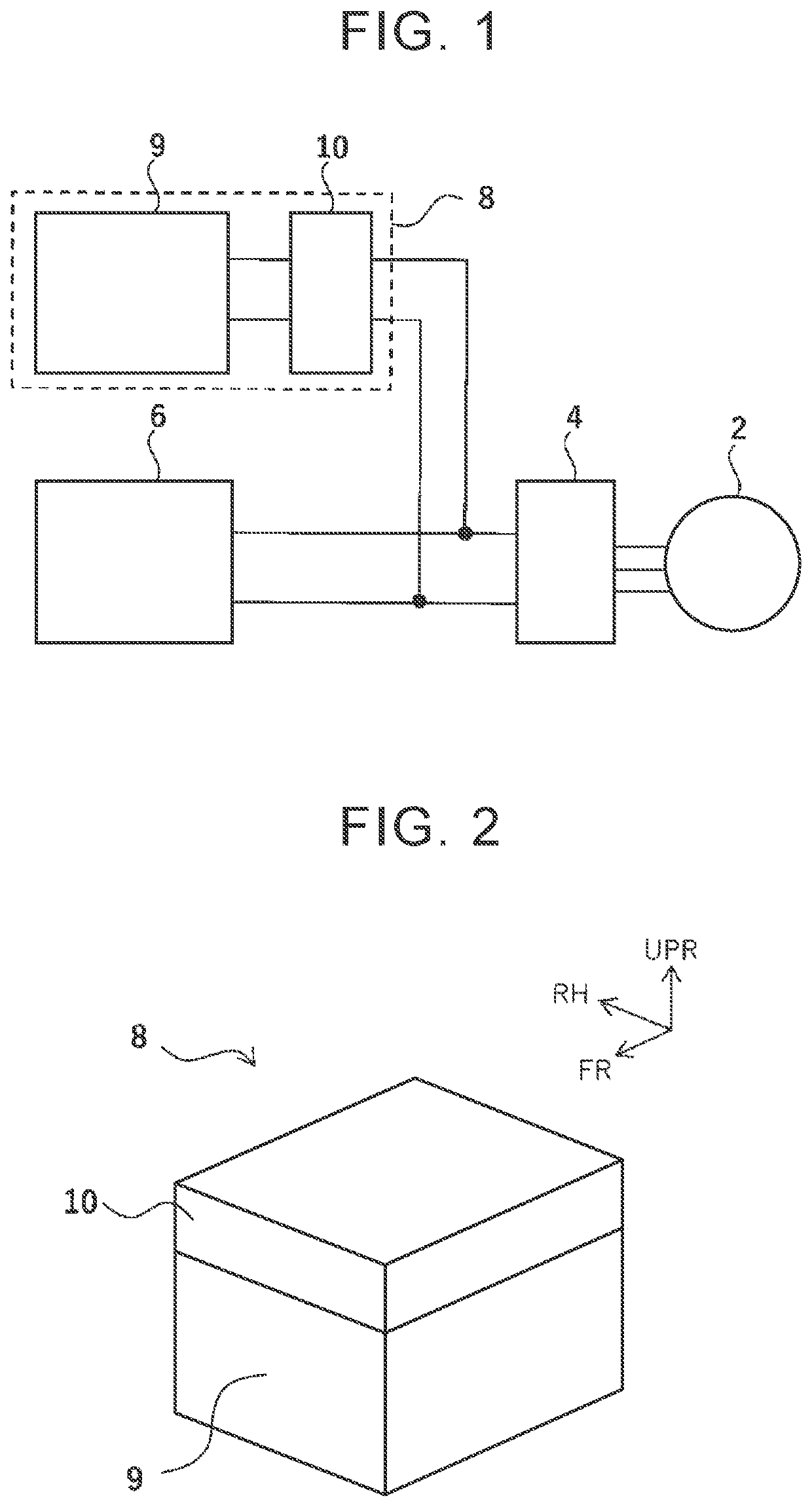
[0062]FIG. 14 is a view illustrating a modification of the positional relationship between the FC stack and the FDC. An FC unit 108 in this modification is configured such that an FDC 110 is attached to a lateral side of an FC stack 109. Accordingly, in this modification, a mounting surface where the FDC 110 is provided on the FC unit 108 is not a horizontal surface and is a vertical surface. The FDC 100 according to the first embodiment and the FDC 70 according to the second embodiment may be provided in an FC unit like the FDC 110 illustrated in this modification.

[0063]In the meantime, the form of the power train system of the fuel cell vehicle as illustrated in FIG. 1 is called a battery direct c...


PUM

PropertyMeasurementUnit
heat-resistant upper limit temperaturesaaaaaaaaaa
voltageaaaaaaaaaa
output voltageaaaaaaaaaa

Abstract

A current sensor is provided on a bus bar via which a reactor is connected to a power module. The reactor is separated from the current sensor by a partition made of metal having a magnetic shielding effect. An output terminal of the reactor is provided on either one of a surface of the reactor on a first side and a surface of the reactor on a second side, the first side being farther from a mounting surface of a power converter across a plane passing through the center of the reactor, the second side being closer to the mounting surface from the plane.

Description

CROSS-REFERENCE TO RELATED APPLICATION[0001]This application claims priority to Japanese Patent Application No. 2020-043148 filed on Mar. 12, 2020, incorporated herein by reference in its entirety.BACKGROUND1. Technical Field[0002]The present disclosure relates to a power converter to be provided in a fuel cell unit.2. Description of Related Art[0003]As described in Japanese Unexamined Patent Application Publication No. 2012-105369 (JP 2012-105369 A), for example, there has been known a power converter provided in a fuel cell unit. Fuel cell units to be provided in electric vehicles are demanded for further downsizing due to spatial restriction of a mount space in the vehicles. This demand also applies to power converters constituting the fuel cell units.[0004]The power converters include reactors. Due to heat generation by core loss in addition to heat generation by conduction loss of coils, the temperature of the reactors particularly easily becomes high among component parts prov...

Claims


Application Information

Patent Timeline
Patent Type & Authority Patents(United States)
IPC IPC(8): H02M7/00H02M7/48H05K7/20H01M8/04
CPCH02M7/003H01M8/04H02M7/48H05K7/209H05K7/20927H01M2250/20H02M1/00H05K7/20909H02P27/06H02M1/0009H01M16/006H05K9/0037Y02E60/10
Inventor HAYASHI, ATSUSHIYAMASAKI, HIROMIHAYASHI, KAZUKI
Owner DENSO CORP
Why Eureka
Try Eureka