Supercharge Your Innovation With Domain-Expert AI Agents!

Physical quantity detection device and printing apparatus

a detection device and physical quantity technology, applied in the direction of liquid/fluent solid measurement, machines/engines, instruments, etc., can solve the problems of inability to accurately detect the remaining amount of ink in each ink container, and the electrical interference of the electrodes provided at adjacent ink containers

Active Publication Date: 2022-11-01
SEIKO EPSON CORP
View PDF8 Cites 0 Cited by
  • Summary
  • Abstract
  • Description
  • Claims
  • Application Information

AI Technical Summary

Benefits of technology

The solution enables accurate detection of ink levels in each container, preventing electrical interference and ensuring reliable ink level monitoring, thereby preventing unintended ink depletion and improving printing efficiency.

Problems solved by technology

When a configuration in Patent Literature 1 is applied to the ink containers, electrodes provided at adjacent ink containers electrically interfere with each other and a remaining amount of ink in each ink container cannot be accurately detected.

Method used


Image

  • Physical quantity detection device and printing apparatus
  • Physical quantity detection device and printing apparatus
  • Physical quantity detection device and printing apparatus

Examples


first embodiment

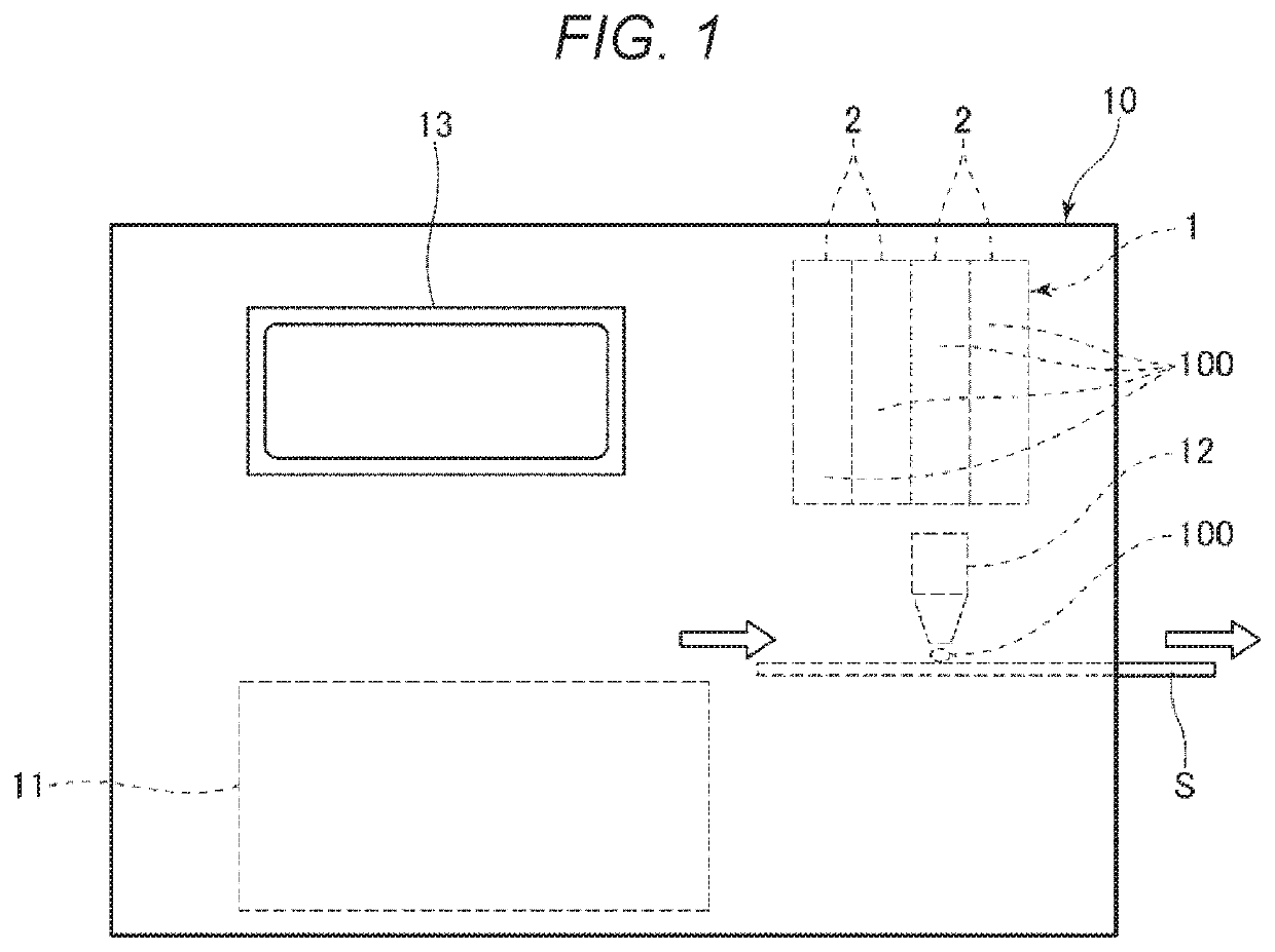
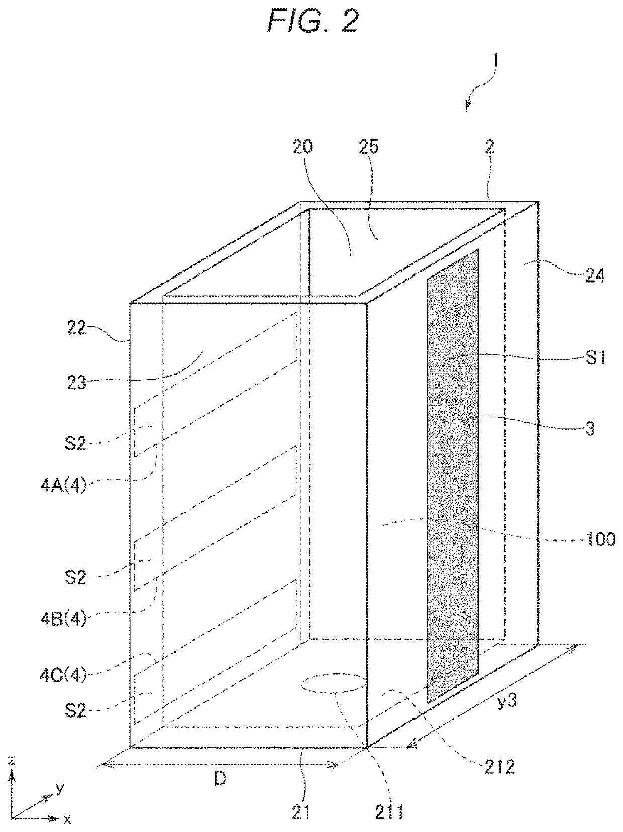
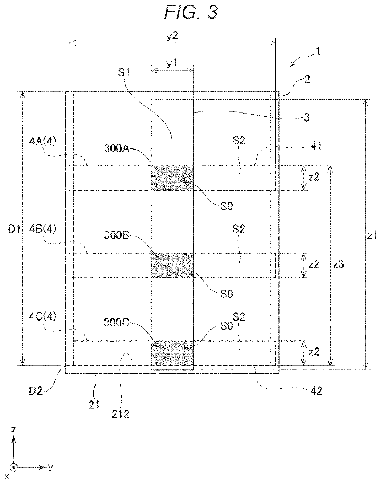
[0024]FIG. 1 is a schematic configuration diagram showing a printing apparatus according to the present disclosure. FIG. 2 is a perspective view showing a container provided in a physical quantity detection device shown in FIG. 1. FIG. 3 is a diagram viewed from an x axis direction in FIG. 2. FIG. 4 is a diagram showing an electrical coupling with an electrostatic capacitance detector as viewed from a y axis direction in FIG. 2. FIG. 5 is a circuit diagram showing the physical quantity detection device shown in FIG. 1. FIG. 6 is a block diagram showing the physical quantity detection device shown in FIG. 1. FIGS. 7 to 10 are graphs showing a temporal change of voltages detected by the electrostatic capacitance detector. FIG. 11 is a diagram showing a positional relationship between a first electrode and a second electrode. FIGS. 12 and 13 are flowcharts showing a control operation performed by a control unit shown in FIG. 6. FIG. 14 is a side view showing an arrangement of a plurali...


PUM

PropertyMeasurementUnit
relative dielectric constantaaaaaaaaaa
separation distanceaaaaaaaaaa

Abstract

A physical quantity detection device including a container that accommodates a detection object formed of a dielectric and whose depth direction is a direction of a z axis when an x axis, a y axis, and the z axis along a vertical direction are set as axes orthogonal to one another, a first electrode provided at an outer side of the container, at least one second electrode that has an elongated shape extending in a direction of the y axis, is provided at an outer side of the container, and is separated from and faces the first electrode in a direction of the x axis, a first insulation layer that covers the first electrode, a second insulation layer that covers the second electrode, and an electrostatic capacitance detector that detects an electrostatic capacitance between the first electrode and the second electrode.

Description

[0001]The present application is based on, and claims priority from JP Application Serial Number 2019-178872, filed Sep. 30, 2019, the disclosure of which is hereby incorporated by reference herein in its entirety.BACKGROUND1. Technical Field[0002]The present disclosure relates to a physical quantity detection device and a printing apparatus.2. Related Art[0003]JP-A-2001-121681 (Patent Literature 1) discloses a technique known as a remaining amount detection unit that detects a remaining amount of ink inside an ink container in a printing apparatus or the like. The remaining amount detection unit disclosed in Patent Literature 1 includes the ink container that contains ink, a pair of electrodes that is provided to face each other via the ink container, and an electric capacitance detection unit that detects an electric signal corresponding to an electrostatic capacitance value between the pair of electrodes. Each electrode has an elongated shape extending in a vertical direction. Ap...

Claims


Application Information

Patent Timeline
Patent Type & Authority Patents(United States)
IPC IPC(8): B41J2/175G01F23/263
CPCB41J2/17566G01F23/263B41J2002/17579
Inventor YONEMURA, TAKAYUKI
Owner SEIKO EPSON CORP
Features
  • R&D
  • Intellectual Property
  • Life Sciences
  • Materials
  • Tech Scout
  • Unparalleled Data Quality
  • Higher Quality Content
  • 60% Fewer Hallucinations
Learn More