Eureka AIR delivers breakthrough ideas for toughest innovation challenges, trusted by R&D personnel around the world.

Oscillating piston pump comprising a one-piece structural element having a first and a second hollow tubular body

a technology of oscillating magnetic piston and hollow tubular body, which is applied in the direction of machines/engines, liquid fuel engines, positive displacement liquid engines, etc., can solve the problems of affecting the smoothness of the pump

Active Publication Date: 2022-11-01
SAUERMANN IND
View PDF14 Cites 0 Cited by
  • Summary
  • Abstract
  • Description
  • Claims
  • Application Information

AI Technical Summary

Benefits of technology

The patent is about a new design for a pump that reduces assembly time and simplifies the architecture of the pump. The design includes two hollow tubular bodies that are made in one piece, which helps to save money and simplify the pump's assembly. The patent also describes a simple and affordable solution for locking the tubular bodies together, which makes it easy to assemble and use the pump.

Problems solved by technology

The resultant manufacture and fitting are therefore relatively complex.
Furthermore, once the pump is assembled, non-negligible transverse stresses may be exerted on the liner 1, in particular on its ends, tending to deform the liner and thus causing it to lose its straightness.
A risk then arises that, during its movement, the piston 5 will rub against the walls of the liner 1 and that its back-and-forth movements are hindered.
This results in a loss of efficiency of the pump and poor hydraulic performance, and even in the risk of wear or blockage.
This is of course problematic, in particular in applications where the pump must operate for long periods of time (several months, or even years) without servicing, and / or where a breakdown could cause overflows.
The manufacture and assembly which result are therefore also relatively complex.
In addition, once the pump assembled, significant transverse stresses can be exerted on the assembly of the four elements, in particular the ends, tending to deform it at the level of the threaded rods, and thus to make it lose its straightness.
This results in a loss of time and a loss of resources (the tubing must generally be changed because it is no longer the right length), and consequently an economic loss for the installer.

Method used


Image

  • Oscillating piston pump comprising a one-piece structural element having a first and a second hollow tubular body
  • Oscillating piston pump comprising a one-piece structural element having a first and a second hollow tubular body
  • Oscillating piston pump comprising a one-piece structural element having a first and a second hollow tubular body

Examples


Embodiment Construction

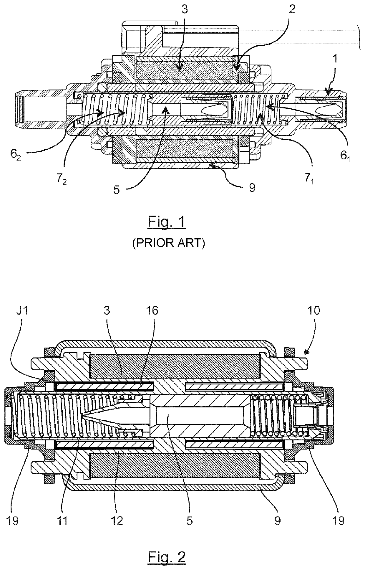
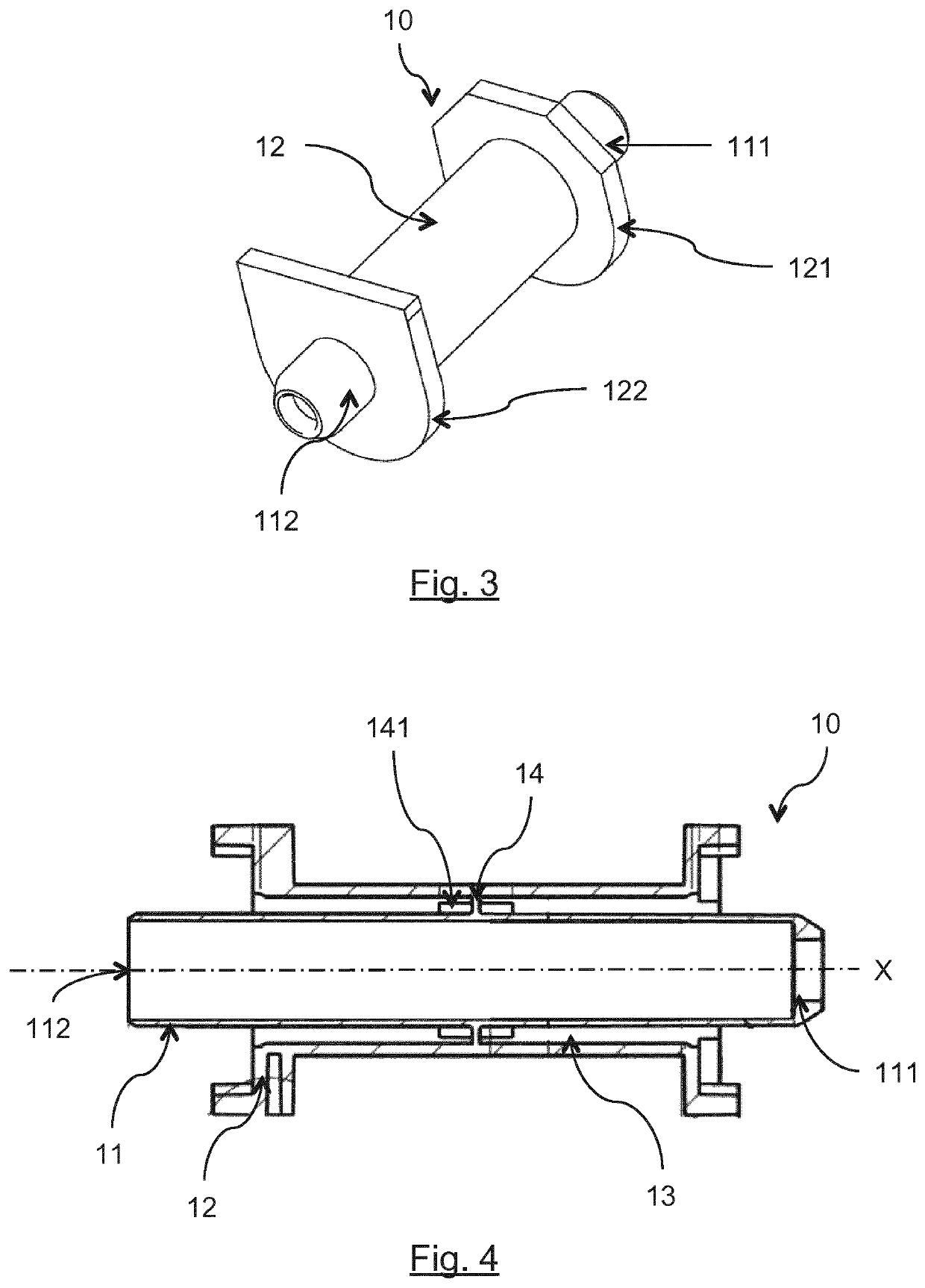
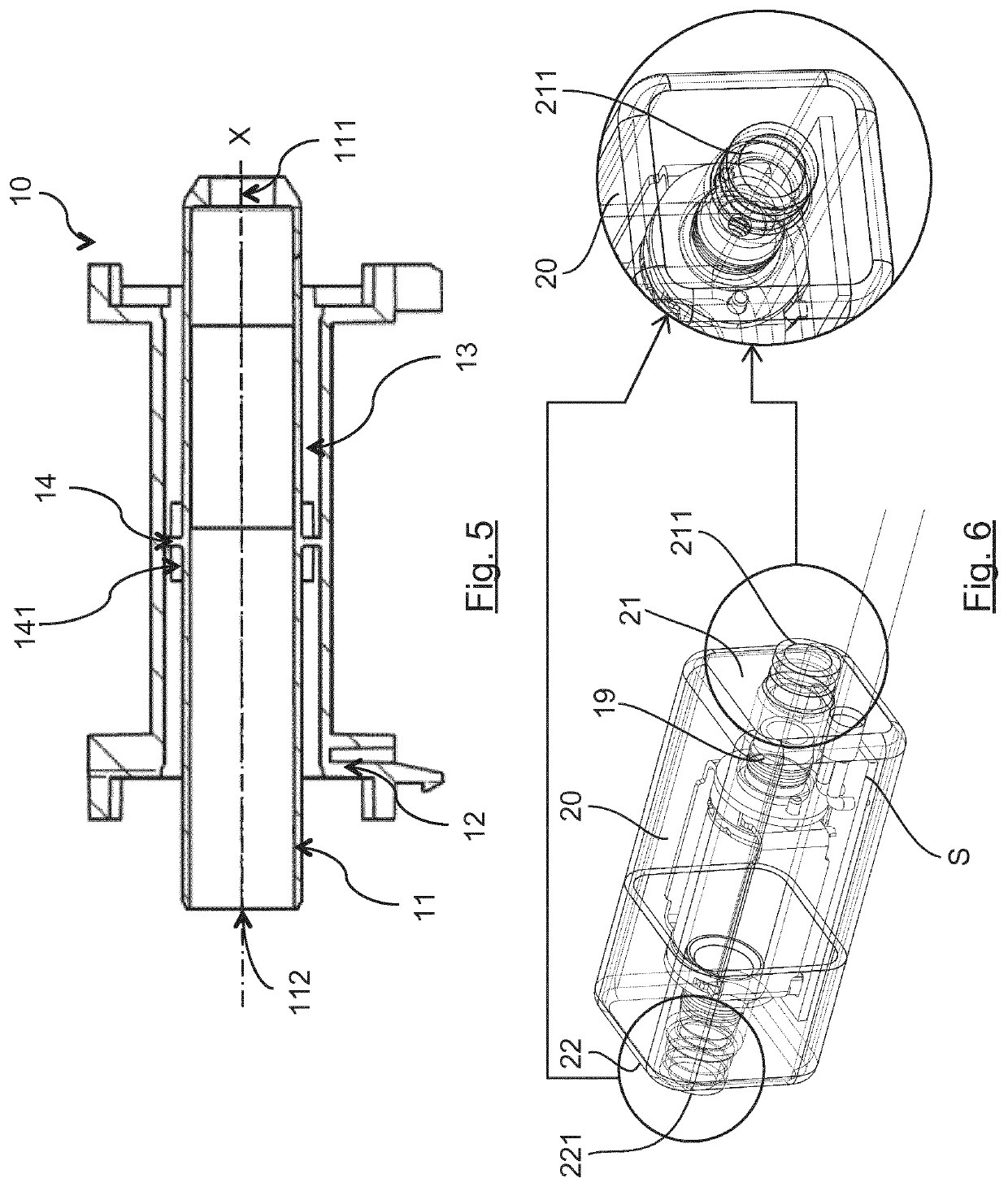
[0068]5.1 General Principle

[0069]The general principle of the invention is based on a new approach to the architecture of an electromagnetic pump with oscillating piston, that is simplified with respect to the pumps of the prior art.

[0070]The oscillating piston pump thus uses, according to the invention, a single element, called the one-piece structural element, comprising a first hollow tubular body, or liner, in which a piston moves, and a second hollow tubular body, or coil former, which extends around the first tubular body and carries a solenoid supplied with an electric current and thus forming a solenoid enabling control of the movement of the piston.

[0071]In other words, the first hollow tubular body and the second hollow tubular body constitute a single and same part. The one-piece structural element, or support, therefore comprises two coaxial hollow tubular bodies.

[0072]The architecture of this pump is therefore greatly simplified with respect to currently existing pumps ...


PUM


Abstract

An oscillating piston pump including: a first hollow tubular body in which a piston moves; a second hollow tubular body extending around the first hollow tubular body, carrying a solenoid that controls the movement of the piston, the first tubular body and the second tubular body forming a one-piece structural element.

Description

1. FIELD OF THE INVENTION[0001]The field of the invention is that of pumping devices for the removal of condensates, intended to be used in systems producing condensates, in particular air-conditioning systems, refrigeration systems, ventilation systems or heating systems.[0002]More particularly, the invention concerns an electromagnetic pump with oscillating magnetic piston.2. TECHNICAL BACKGROUND[0003]Electromagnetic pumps with oscillating pistons are currently used in many applications, including coffee machines, automatic dispensers, steam ironing devices, irrigation systems, air-conditioning systems, the automotive industry, etc.[0004]In these various applications, it is known to use an electromagnetic pump, an example of which is illustrated in FIG. 1.[0005]Such a pump comprises:[0006]a first substantially tubular hollow body 1, or liner, extending along a longitudinal direction[0007]a second substantially tubular hollow body 2, or coil former, extending along a longitudinal d...

Claims


Application Information

Patent Timeline
Patent Type & Authority Patents(United States)
IPC IPC(8): F04B17/04F04B53/10F04B53/16F16B21/18H02K33/10
CPCF04B17/044F04B17/046F04B53/1087F04B53/16F16B21/186H02K33/10F04B17/04F04B53/162H02K33/16
Inventor SARDET, FRANCOISDE GEA, OLIVIERBOUSSUGE, JEAN-BAPTISTECLEVELAND, DIDIER
Owner SAUERMANN IND
Why Eureka
Eureka Blog
Learn More