

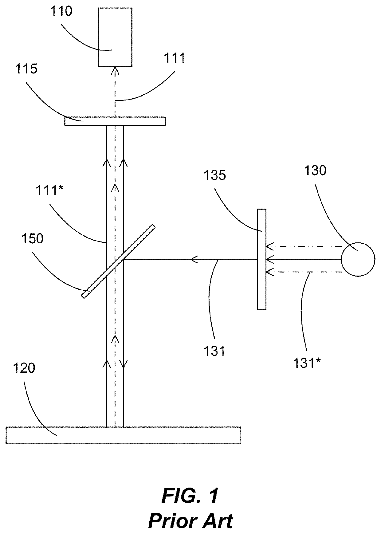
System and method for synchronized fluorescence capture
a fluorescence capture and synchronization technology, applied in the field of optical microscopes, can solve the problems of inability to accurately image more than one fluorescence emission spectrum in rapidly moving specimens, complex optical arrangements, and limited arrangement to a small field, so as to achieve accurate correlation of fluorescence measurements
- Summary
- Abstract
- Description
- Claims
- Application Information
AI Technical Summary
Benefits of technology
Problems solved by technology
Method used
Image

Examples
Embodiment Construction
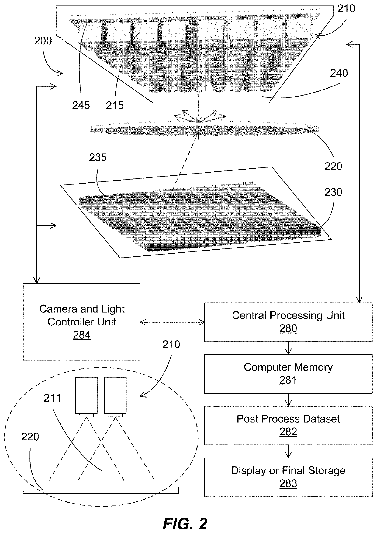
[0011]In some embodiments, the present invention discloses systems and methods for a fluorescence microscope with the ability to synchronize the captured fluorescence signals through the process of multi-channel imaging.
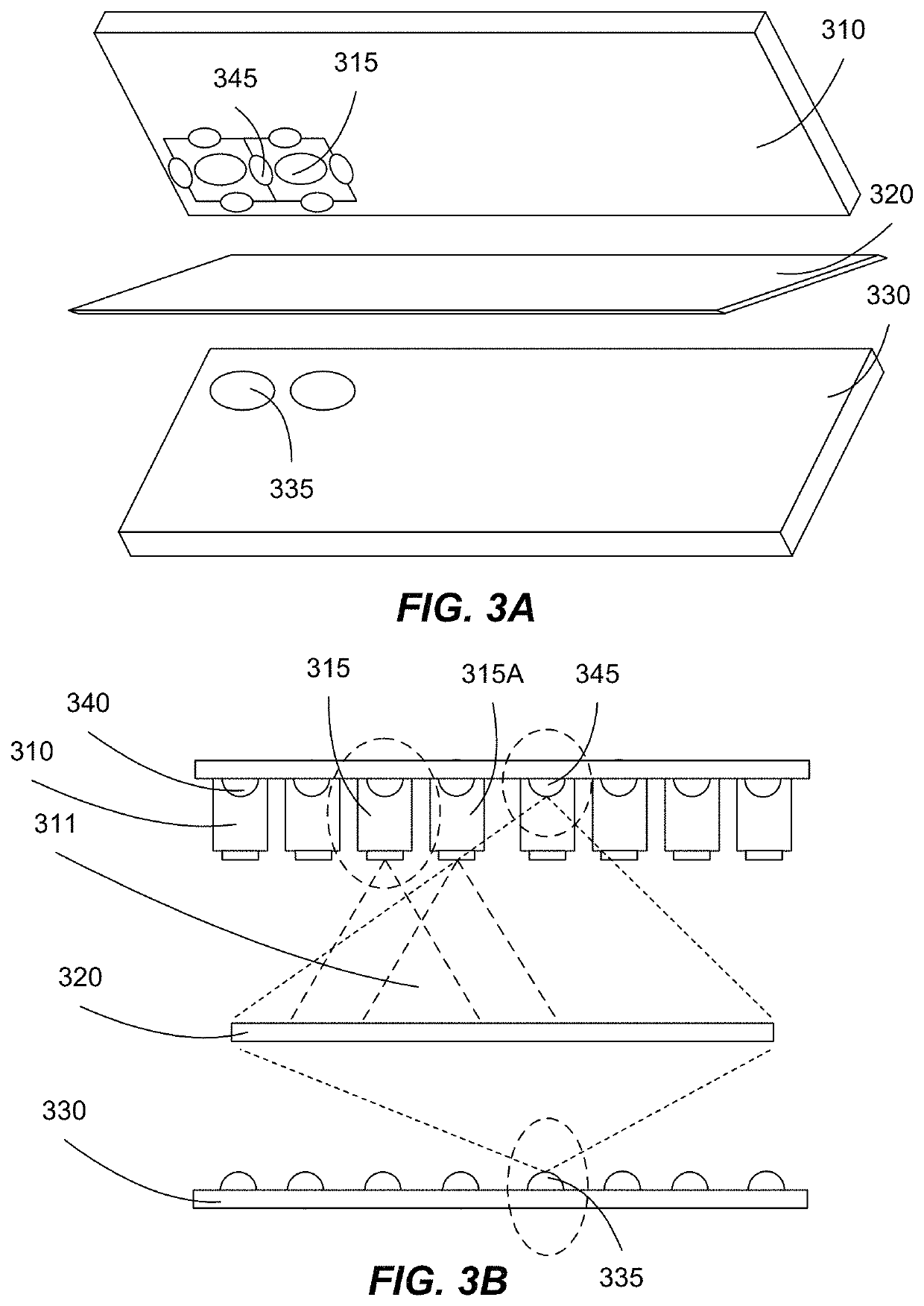
[0012]In some embodiments, the present invention discloses a multi-channel computational fluorescence microscope system, which can capture simultaneously fluorescence caused by multiple fluorescence excitation sources and can analyze the data, including synchronizing and correlating the interaction between various fluorescence elements and also with the surrounding morphologies. The multi-channel fluorescence capability of the microscope can be achieved by partitioning the camera array and the illumination source into multiple imaging channels, with each channel observing a similar area of the sample but designed to generate and obtain different fluorescence excitation, emission and interaction.
[0013]In some embodiments, the multi-channel computational fluorescence m...
PUM
| Property | Measurement | Unit |
|---|---|---|
| wavelengths | aaaaa | aaaaa |
| wavelengths | aaaaa | aaaaa |
| wavelengths | aaaaa | aaaaa |
Abstract
Description
Claims
Application Information