Inspection device and method

a panel body and inspection device technology, applied in the field of inspection, can solve the problems of expensive replacement and time-consuming after the initial replacement of the panel body, and achieve the effect of improving the quality of the panel body and reducing the cost of replacemen

Active Publication Date: 2022-11-22
ULTRASONIC TECH INC
View PDF19 Cites 0 Cited by
  • Summary
  • Abstract
  • Description
  • Claims
  • Application Information

AI Technical Summary

Benefits of technology

The invention relates to a device for testing the integrity of a panel body. The device includes a base that can be positioned between a first engagement position and a non-engagement position. The base defines a first panel body deflection when the chamber is evacuated and the non-engagement position separates the base from the panel body. The base can also be pivoted to an alter angular orientation with respect to the panel body. A transfer device is used to position the panel body from the base to a second base, which defines a second chamber for testing the panel body. The second base also defines a second panel body deflection when the chamber is evacuated. The device increases the homogeneous stress distribution within the panel body and reduces the evacuation pressure to facilitate testing for defects.

Problems solved by technology

Once these panel bodies are installed it can be extremely time-consuming and expensive to replace them thereafter.

Method used


Image

  • Inspection device and method
  • Inspection device and method
  • Inspection device and method

Examples


Embodiment Construction

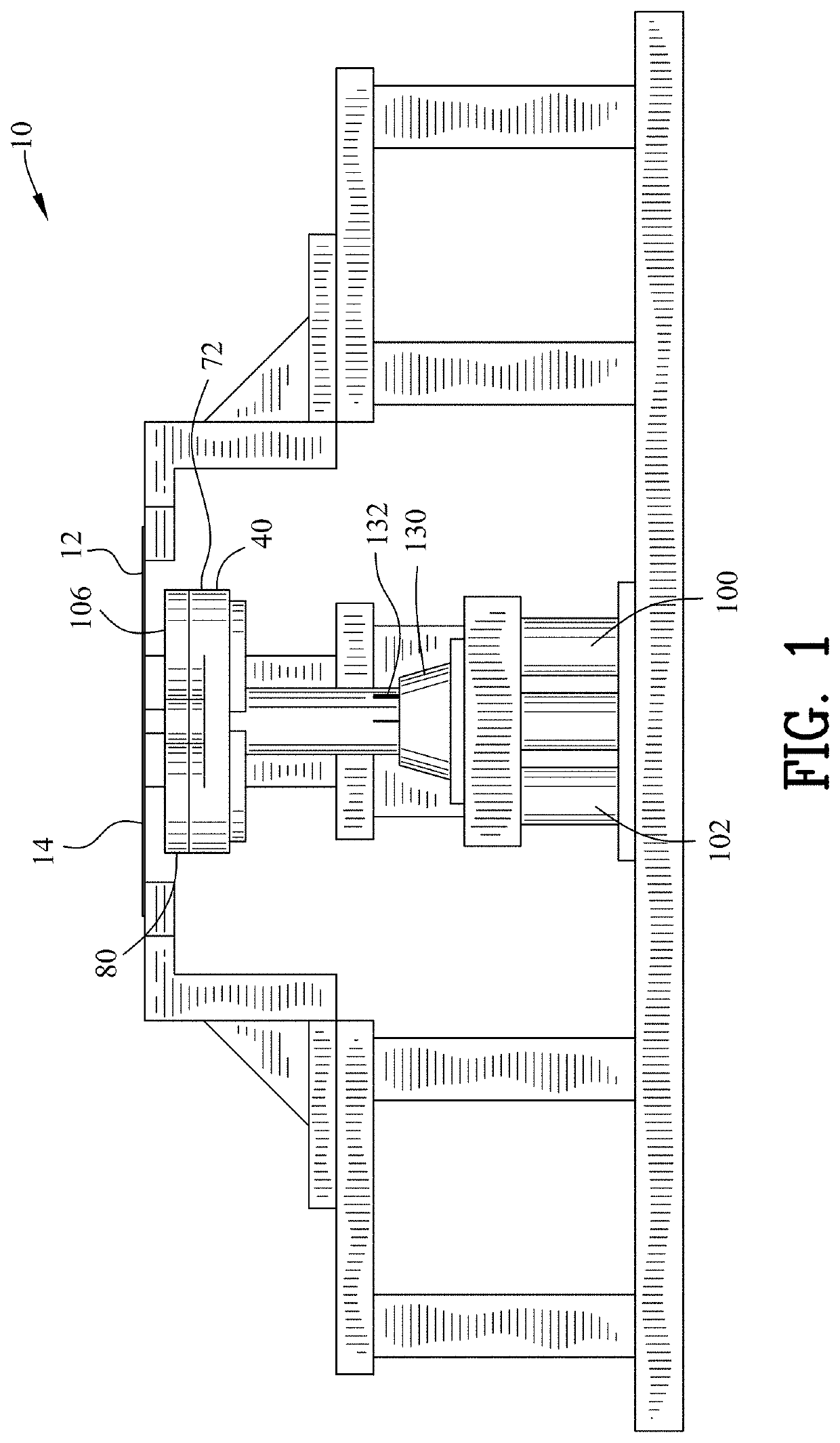
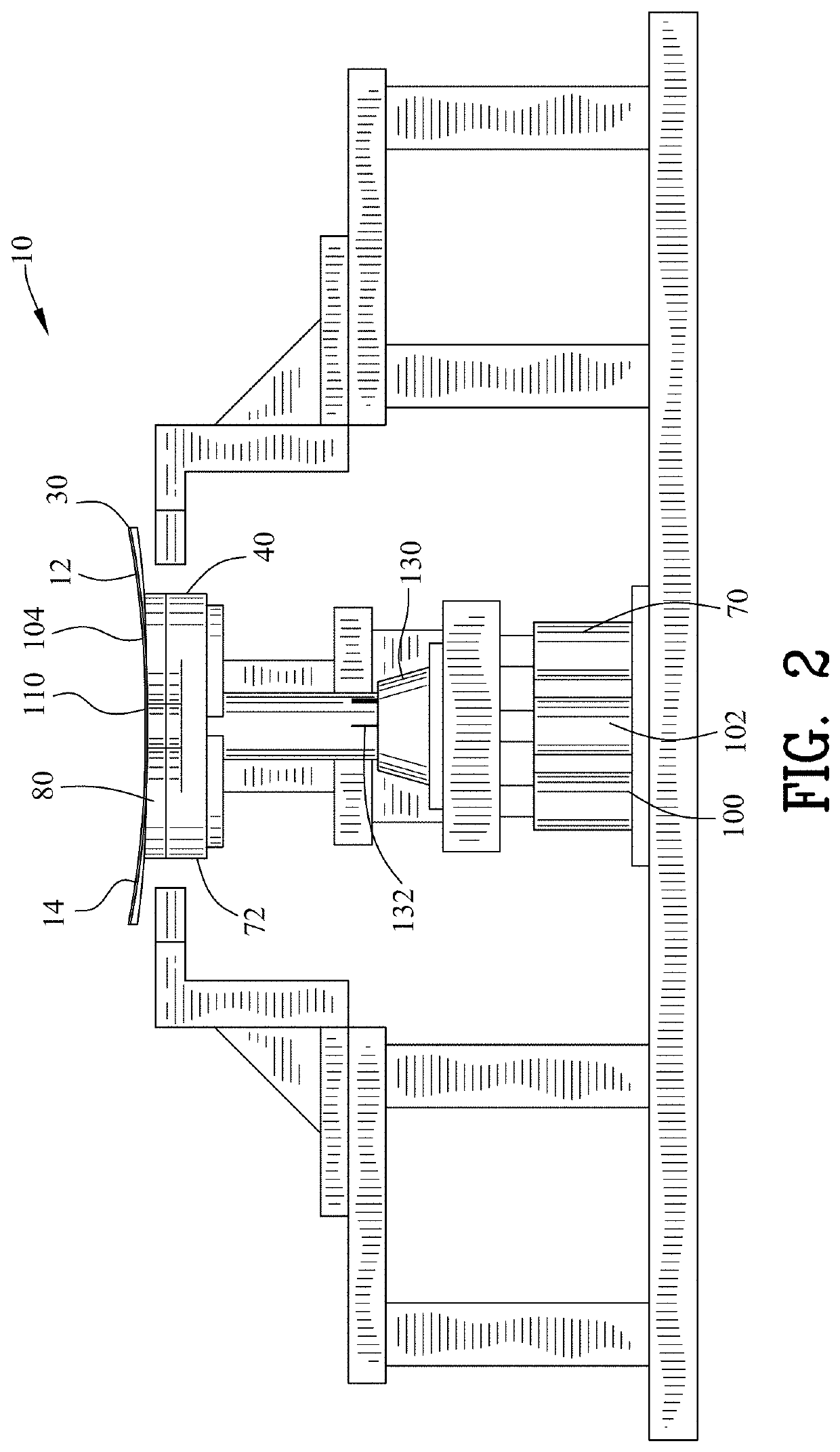
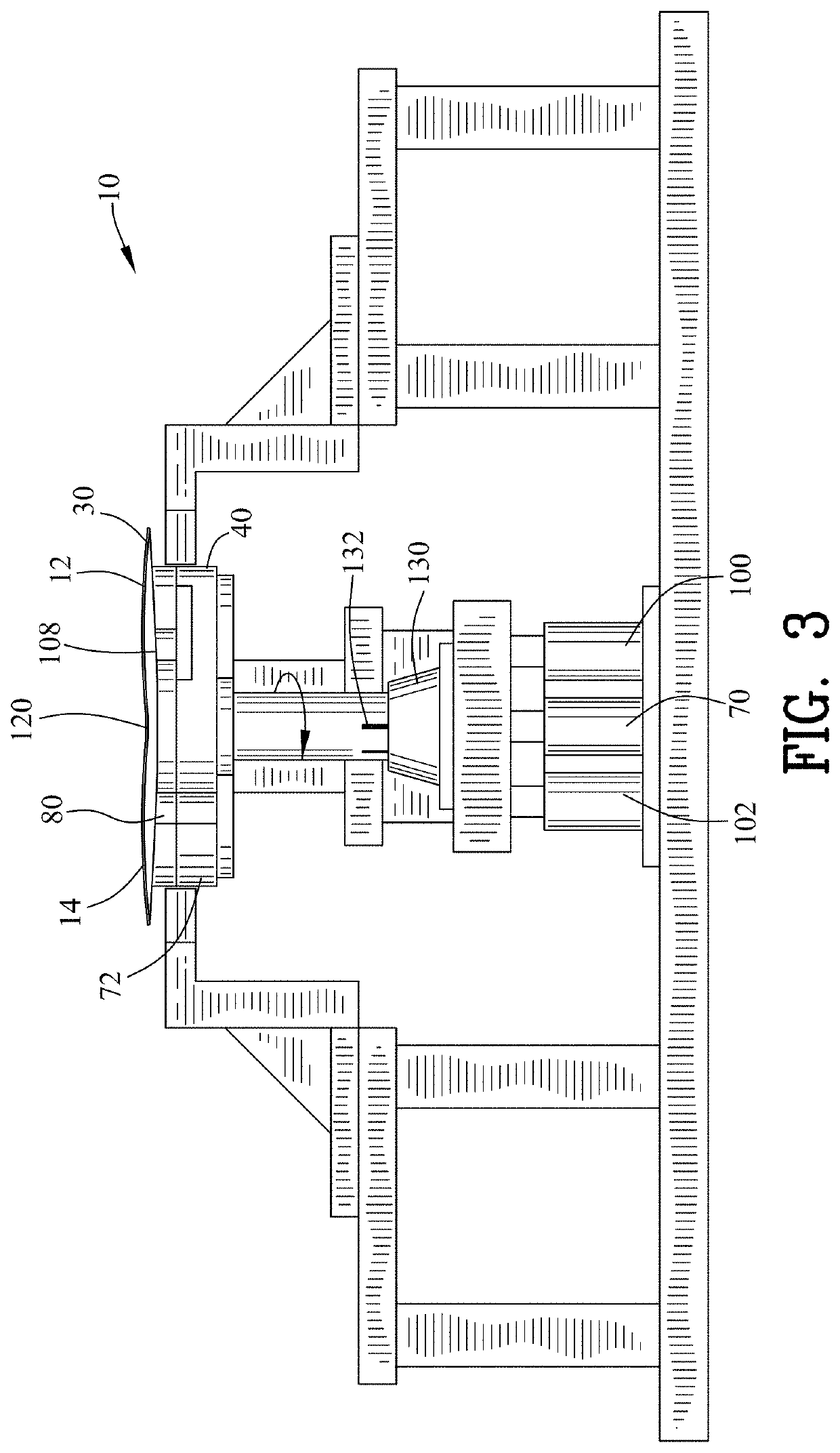
[0054]FIGS. 1-29 illustrate an inspection device 10 for producing a deformation 30 in a panel body 12 and revealing a defect 32 in the panel body 12. The defect 32 may include cracks, weakened areas or other imperfections within the panel body 12. The defect 32 may be visible or non-visible to the human eye.

[0055]The panel body 12 may include a solar wafer 14 as shown in FIGS. 1-5 and 13-15. For example, the solar wafer 14 may include solar cells (Si). The panel body 12 may also include a plurality of solar wafers 16 that are connected by ribbons 18 as shown in FIGS. 6-10. The panel body 12 may alternatively include a ceramic plate, for example a ceramic plate used in solid oxide fuel cells (SOFC). The panel body 12 may alternatively include round shaped electronic wafers such as LiTaO3 (LT) wafer, LiNbO3 wafer, GaAs wafer, GaN wafer or other electronic waters.

[0056]The panel body 12 may include glass 20. For example, the glass 20 may include an automobile windshield or window 22 as...


PUM


Abstract

An inspection device and method produces a deformation in a panel body and reveals a defect in the panel body. A base and a collar define a chamber. A vacuum device connects with the chamber for evacuating the chamber after the panel body is positioned adjacent to the collar and deflects the panel body into the chamber for propagating the defect in the panel body.

Description

CROSS-REFERENCE TO RELATED APPLICATIONS[0001]This application claims benefit of U.S. Patent Provisional application No. 62 / 822,776 filed Mar. 22, 2019. All subject matter set forth in provisional application No. 62 / 822,776is hereby incorporated by reference into the present application as if fully set forth herein.FIELD OF THE INVENTION[0002]This invention relates to the inspection and more particularly, this invention relates to an inspection device and method for a panel body.BACKGROUND OF THE INVENTION[0003]Various types of panel bodies are utilized in a multitude of industries including but not limited to electrical, construction, body armor, hardware or other applications. Once these panel bodies are installed it can be extremely time-consuming and expensive to replace them thereafter. An inspection device for inspecting the panel bodies before installation and utilization may be both time-saving and greatly reduce the overall expense of the panel bodies. There is a need for an...

Claims


Application Information

Patent Timeline
IPC IPC(8): G01N19/08G01N3/20G01N3/10G01N33/38
CPCG01N19/08G01N3/20G01N3/10G01N33/386G01N2203/0046G01N2203/0258G01N2203/0417G01N2203/0282
Inventor OSTAPENKO, SERGEIRODRIGUES, CHADTARASOV, IGOR
Owner ULTRASONIC TECH INC
Why Eureka
Try Eureka