
EMC test system and EMC test method using LiFi

Active Publication Date: 2022-11-22
ROHDE & SCHWARZ GMBH & CO KG
View PDF3 Cites 0 Cited by
  • Summary
  • Abstract
  • Description
  • Claims
  • Application Information

AI Technical Summary

Benefits of technology

The patent describes a new technology called LiFi that uses light to transmit data between devices, including in areas where radio signals may be difficult. This technology allows for faster and safer data transmission, without generating interference or requiring cable calibration. As a result, the testing effort is reduced and the cost of setting up an EMC test chamber goes down.

Problems solved by technology

This is reached by limiting the unintentional generation, propagation and reception of electromagnetic energy, which may cause unwanted effects such as electromagnetic inference (EMI).
However, these cables are expensive and fragile.

Method used


Image

  • EMC test system and EMC test method using LiFi

Examples


Embodiment Construction

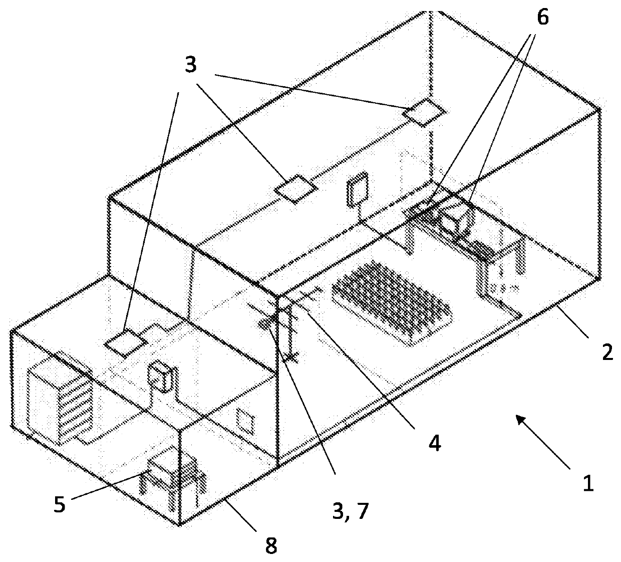
[0028]As already described above, EMC testing is required to confirm that an electrical or electronic device or a system meets the required standards. In particular, EMC testing is necessary to ensure that the electrical or electronic device or system does not emit a large amount of EMI.

[0029]Such devices, also called DUT, are positioned for the EMC testing in a corresponding EMC test chamber, which also comprises for example an antenna or other measurement equipment inside the EMC test chamber.

[0030]Until now, this measurement equipment is connected to each other and to a measurement computer / measurement processing unit for evaluating, analyzing and displaying the measurement values, via RF cables or fiber optic cables. These cables, however, are expensive and fragile and RF cables for example further need a frequent calibration. Further, such cables are possible sources for emissions / interferences and fiber optic cables should not be bend and should be laid out in a straight line....


PUM


Abstract

An EMC test system (1) and an EMC test method performed in the EMC test system (1) for testing a DUT (6), wherein the EMC test system (1) comprises an EMC test chamber (2), wherein the DUT (6) is positioned in the EMC test chamber (2), at least one measurement equipment (4) positioned in the EMC test chamber (2) and communication means (3) using LiFi for transmitting and receiving measurement data and / or control data by the measurement equipment (4).

Description

FIELD OF THE INVENTION[0001]The present invention relates to an electromagnetic compatibility (EMC) test system and an EMC test method performed in the EMC test system for testing a device under test (DUT). The EMC test system comprises an EMC test chamber, wherein the DUT is positioned in the EMC test chamber, at least one measurement equipment positioned in the EMC test chamber and communication means using light fidelity (LiFi) for transmitting and receiving measurement data and / or control data by the measurement equipment.BACKGROUND[0002]EMC is the ability of electrical or electronic devices / equipment and systems to operate in their electromagnetic environment without impairing their functions and without faults. This is reached by limiting the unintentional generation, propagation and reception of electromagnetic energy, which may cause unwanted effects such as electromagnetic inference (EMI). EMC ensures the correct operation in a common electromagnetic environment.[0003]For t...

Claims


Application Information

Patent Timeline
IPC IPC(8): H04B10/00G01R31/00H04B10/116G01R31/28H04B10/50H04B10/43
CPCG01R31/002G01R31/2862H04B10/116H04B10/43H04B10/502
Inventor ARAOJO, ERIKMAGPANTAY, ANTHONY
Owner ROHDE & SCHWARZ GMBH & CO KG
Learn More