Method for aligning camera lens with light source

Active Publication Date: 2022-11-22
PRIMAX ELECTRONICS LTD
View PDF2 Cites 0 Cited by
  • Summary
  • Abstract
  • Description
  • Claims
  • Application Information

AI Technical Summary

Benefits of technology

[0007]The present invention provides a method for aligning a camera lens with a light source. Especially, the aligning method is applied in the assembling stage. Consequently, the illumination area and location of the light source and the shooting area and location of the camera lens match each other. By usin

Problems solved by technology

If the match between the light source and the camera lens is not good, for example there is a misalignment between the light source and the camera lens, a portion of the shooting area of the camera lens cannot be used.
However, this method is unable to confirm whether the illumination area and location of the light source and the shooting a

Method used


Image

  • Method for aligning camera lens with light source
  • Method for aligning camera lens with light source
  • Method for aligning camera lens with light source

Examples


first embodiment

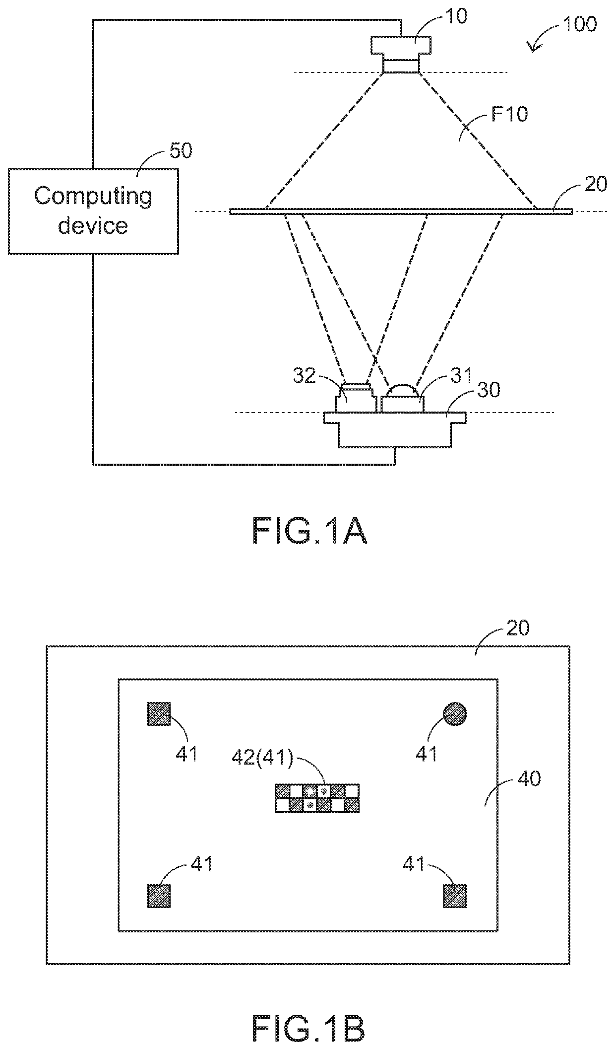
[0018]The present invention provides a method for aligning a camera lens with a light source. the aligning method will be described as follows. FIG. 1A is a schematic planar view illustrating an aligning system using a method for aligning a camera lens with a light source according to an embodiment of the present invention. As shown in FIG. 1A, the aligning system 100 comprises an alignment element 20, a reference camera 10 and a fixture 30. In accordance with a feature of the present invention, the planes where the alignment element 20, the reference camera 10 and the fixture 30 are located are in parallel with each other, and the alignment element 20 is arranged between the reference camera 10 and the fixture 30. That is, the reference camera 10 and the fixture 30 are on two opposite sides of the alignment element 20.

[0019]In this context, the reference camera 10 is an external camera that has passed the test and is confirmed to have good performance. Consequently, the reference c...

second embodiment

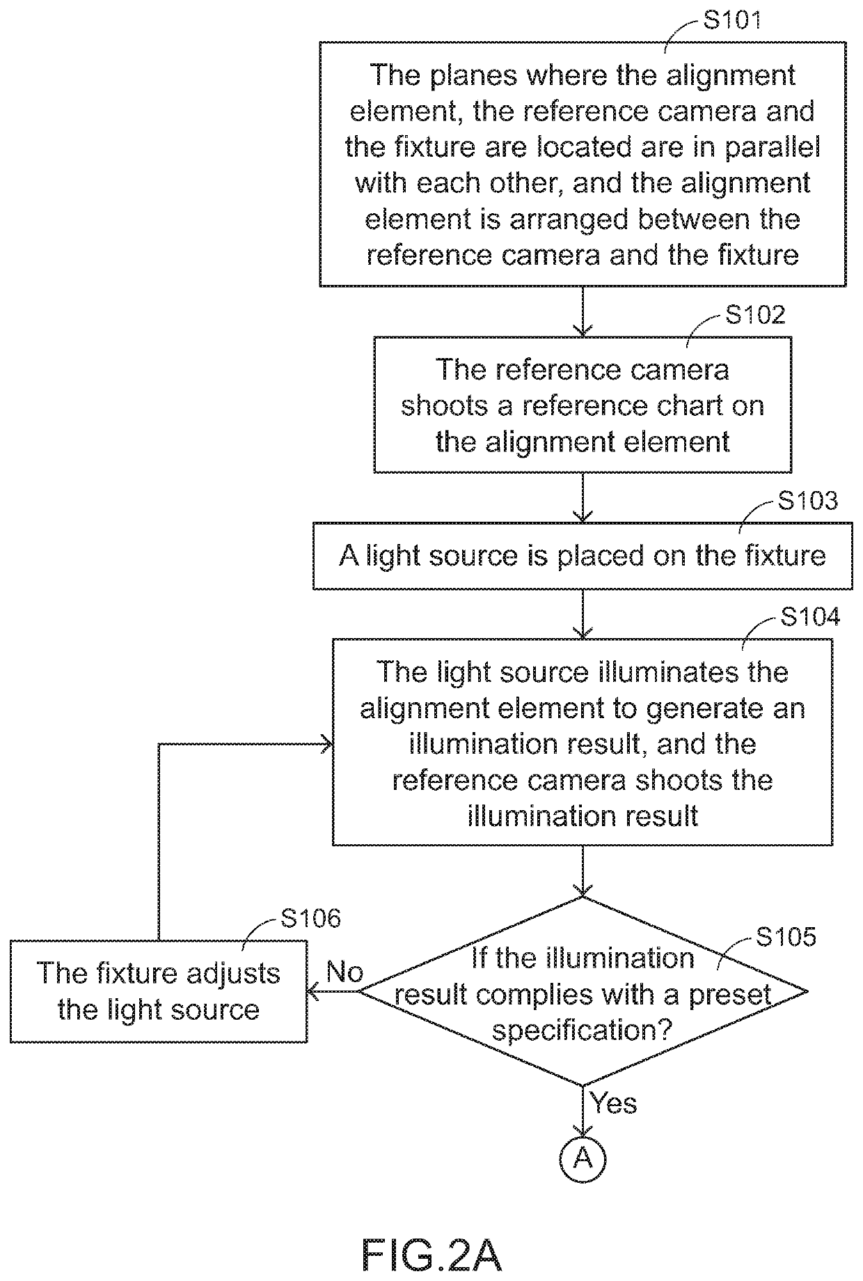
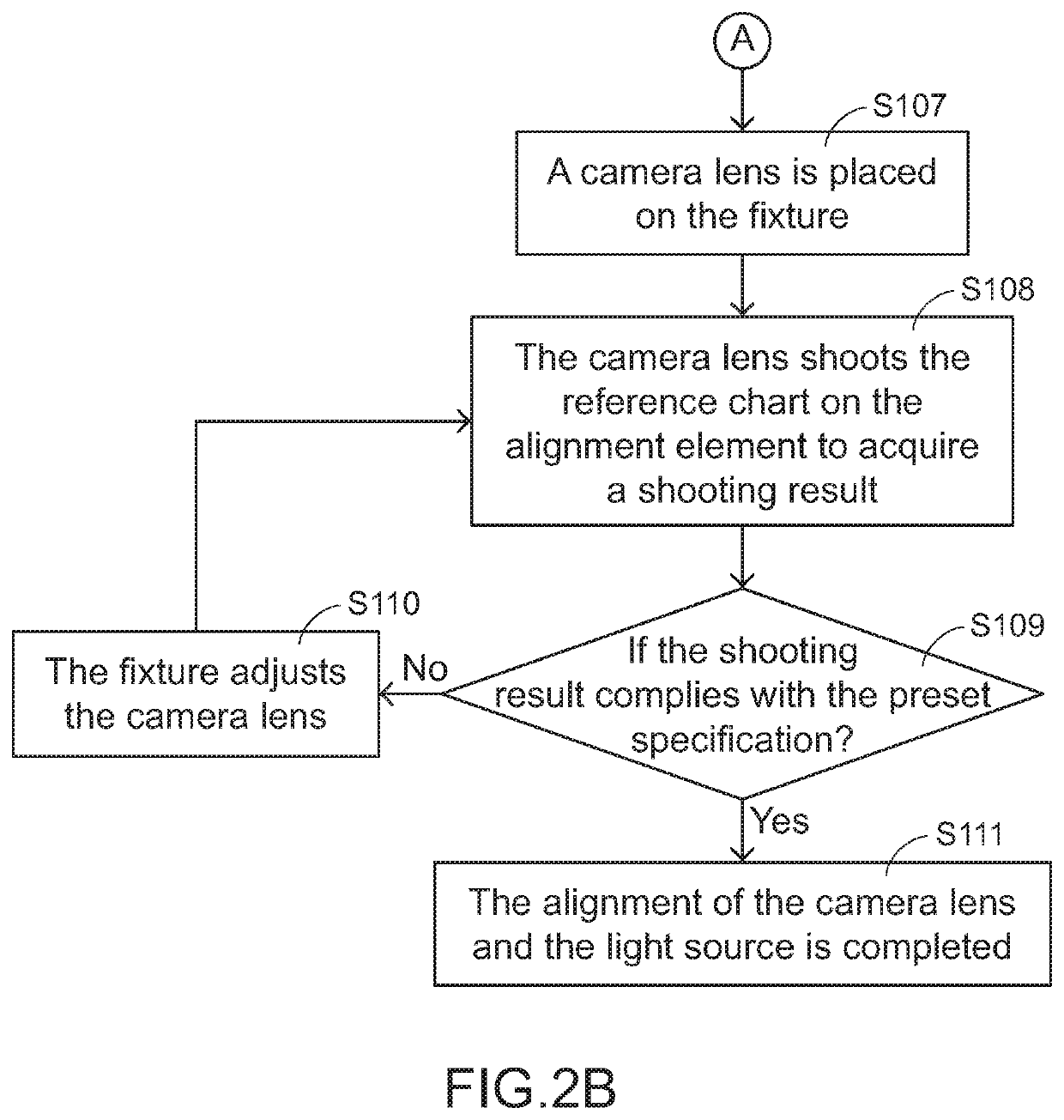
[0052]FIG. 4A and FIG. 4B are the flowcharts illustrating a method for aligning a camera lens with a light source according to the present invention. Firstly, the planes where the alignment element 20, the reference camera 10 and the fixture 30 are located are in parallel with each other, and the alignment element 20 is arranged between the reference camera 10 and the fixture 30 (Step S201). Then, the reference camera 10 shoots a reference chart 40 on the alignment element 20 (Step S202). Then, a camera lens 32 is placed on the fixture 30 (Step S203). Then, the camera lens 32 shoots the reference chart 40 on the alignment element 20 to acquire a shooting result (Step S204). Then, a step S205 is performed to judge whether the shooting result complies with a preset specification represented by the reference chart 40 (Step S205). If the shooting result does not comply with the preset specification, the fixture 30 adjusts the camera lens 32 (Step S206). Whereas, if the shooting result c...


PUM


Abstract

A method for aligning a camera lens with a light source is provided. The method is used in an aligning system. The aligning system includes an alignment element, a reference camera and a fixture. Firstly, the reference camera shoots a reference chart on the alignment element. Then, the light source is placed on the fixture. The light source illuminates the alignment element to generate an illumination result. The reference camera shoots the illumination result. If the illumination result does not comply with a preset specification represented by the reference chart, the fixture adjusts the light source. Then, the camera lens is placed on the fixture. Then, the camera lens shoots the reference chart on the alignment element to acquire a shooting result. If the shooting result does not comply with the preset specification, the fixture adjusts the camera lens.

Description

FIELD OF THE INVENTION[0001]The present invention relates to a method for aligning a camera lens with a light source, and more particularly to a method for aligning the illumination area and location of a light source with the shooting area and location of a camera lens in an assembling stage.BACKGROUND OF THE INVENTION[0002]With the gradual development of the 3D image sensing technology, many mobile electronic devices such as digital cameras, tablet computers, smart phones, smart watches or wearable electronic devices are gradually equipped with 3D image sensing modules as camera lenses and light sources.[0003]Nowadays, the 3D image sensing technologies mainly include a stereo vision technology, a structured light technology, a time of flight (TOF) technology, and the like. Moreover, depending on the applications, one or plural camera lenses or one or plural light sources are configured as a 3D image sensing module according to the design of the 3D image sensing technology. For exa...

Claims


Application Information

Patent Timeline
IPC IPC(8): H04N17/00H04N5/225G02B7/00H04N5/235
CPCH04N17/002G02B7/003H04N5/2256H04N5/2351H04N5/2354H04N23/56H04N23/55H04N23/71H04N23/74
Inventor WANG, HSIU-WENLIN, CHIH-WEN
Owner PRIMAX ELECTRONICS LTD
Why Eureka
Try Eureka