Method of manufacturing a diffuser master using a blasting agent

a blasting agent and manufacturing method technology, applied in the field of optical elements, can solve the problems of inherently destroying the master diffuser, requiring a sterile environment, and particular methods of creating the diffuser are highly labor-intensive,

Inactive Publication Date: 2001-05-24
PHYSICAL OPTICS CORP
View PDF0 Cites 68 Cited by
  • Summary
  • Abstract
  • Description
  • Claims
  • Application Information

AI Technical Summary

Benefits of technology

[0016] In another embodiment, the acid or alkali etching agent also includes a plurality of particles mixed therein each having a size, a shape and a mass. The particles enhance the etching reaction between the substrate body and the acid or alkali agent by forming deeper depressions where the particles are located on the first side of the substrate body. In another embodiment, a pressure may be applied to the first side of the substrate body while the acid or alkali agent and particles are disposed thereon to further enhance penetration of the particles into the first side of the substrate body as the acid or alkali agent reacts with the substrate body material.

Problems solved by technology

Many of these methods inherently destroy the master diffuser when creating the submasters.
This particular method of creating a diffuser is highly labor intensive, requires use of many different materials, requires performing a number of steps, and must be conducted in a sterile environment.
Again, this process is costly, labor intensive, wasteful of material and requires a sterile environment.
Another significant problem with each of these methods is that the submasters or final optical products created from the master optical elements are made from materials such as plastics, epoxies, or polycarbonate composites and exhibit relatively poor long-term characteristics.
These materials are also not suited for use near extremely high temperature light sources because they have relatively low melting or softening temperatures when compared to other more durable materials.

Method used


Image

  • Method of manufacturing a diffuser master using a blasting agent
  • Method of manufacturing a diffuser master using a blasting agent

Examples


Embodiment Construction

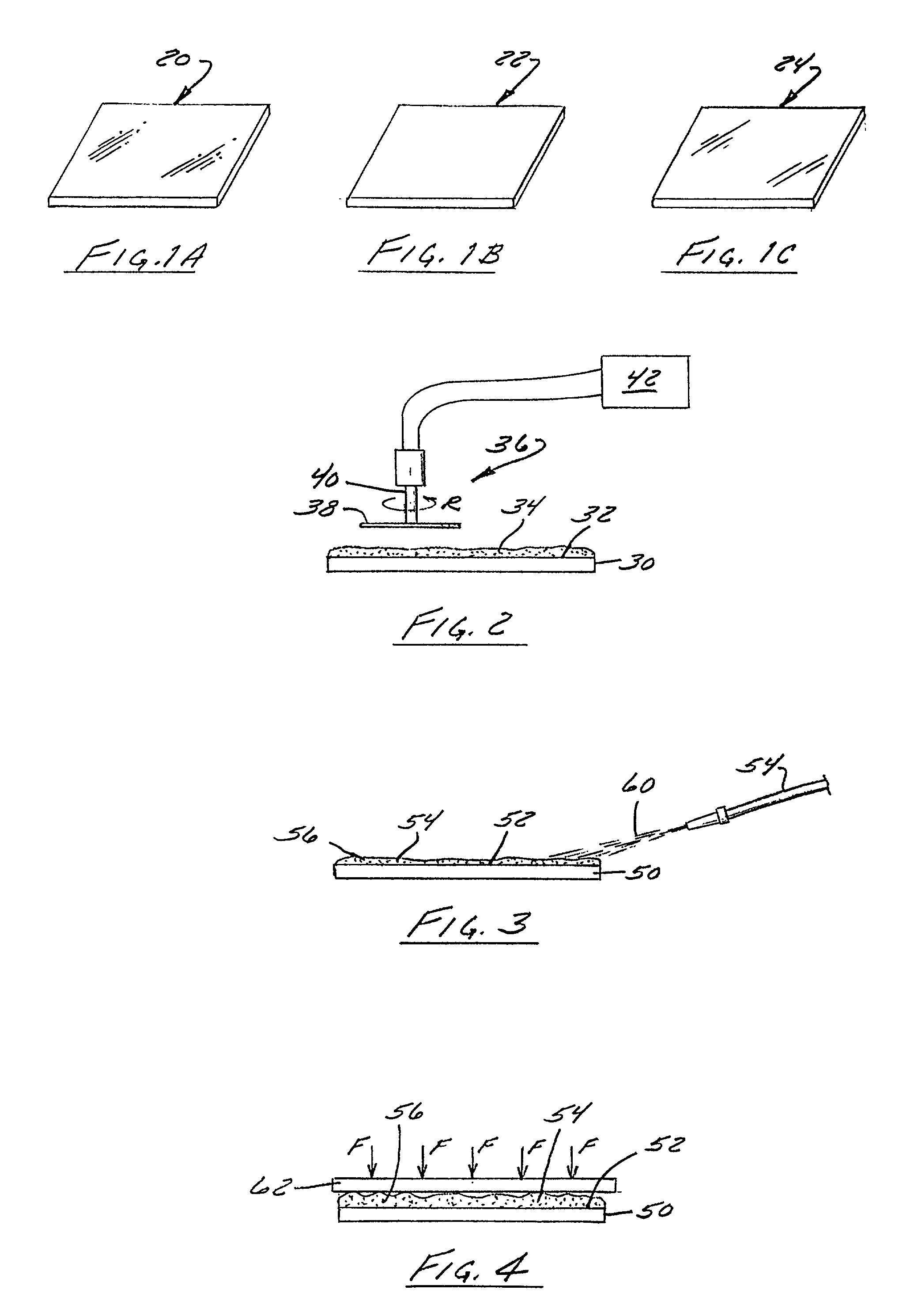
[0035] Referring now to the drawings, FIGS. 1A-1C illustrate several simplified elevational perspective views of diffusers formed by one of the methods of the present invention. The present invention may be utilized to form diffusers from substrate materials such as plastics, glass or metal. The methods are appropriate for forming diffusers from conventional diffuser materials such as epoxy, polycarbonate, polyester, acrylic, nylon, polystyrene, tetrafluoroethylene, polyimide, polyvinyl chloride, polymethyl methacrylate, TPX.TM., ARTON.TM., and other plastic materials but also may be utilized to form diffusers from much more durable materials such as glass and metal for which previous methods were not suitable. Glass materials that can be used include light barium crown, phosphate crown, crown, flint, extralight flint, light flint, fused silicon, and borosilicate. FIG. 1A illustrates a glass diffuser 20 constructed according to one embodiment of the present invention. FIG. 1B illust...


PUM

PropertyMeasurementUnit
diametersaaaaaaaaaa
diameteraaaaaaaaaa
sizesaaaaaaaaaa

Abstract

A diffuser master is provided which is manufactured mechanically instead of holographically. The master can be made from a suitable substrate including relatively hard materials such as plastic, glass or metal. A substrate having a first side is worked to form a diffuser surface relief structure thereon. The substrate can be buffed using a buffing agent of a selected grit in order to form surface scratches in the first side of the substrate. The substrate can also be blasted with shot particles in order to form indentations and depressions in the first side. The substrate can alternatively be acid or alkali etched in order to form surface irregularities in the first side. The scratches, depressions or irregularities can be formed in order to create a desired surface relief and hence desired diffuser output characteristics.

Description

[0001] 1. Field of the Invention[0002] The present invention relates generally to optical elements, and more particularly to a non-Lambertian diffuser fabricated using mechanical means instead of light and mechanical methods for fabricating the diffuser.[0003] 2. Description of the Related Art[0004] Methods for manufacturing and replicating optical components such as a master diffuser exhibiting desired light diffusing characteristics are well known. Many of these methods involve creating a master diffuser by exposing a photoresist material to a source of light and then replicating this master diffuser into one or more submasters of a more durable nature. Many of these methods inherently destroy the master diffuser when creating the submasters. There are also other methods of making replicas of a master diffuser which contain the optical features in the master without destroying the master diffuser. With each of these methods, the master diffuser is initially created optically. Subm...

Claims


Application Information

Patent Timeline
Patent Type & Authority Applications(United States)
IPC IPC(8): B29D11/00G02B5/02
CPCG02B5/0221G02B5/0226G02B5/0268G02B5/02
Inventor SAVANT, GAJENDRA D.YU, KEVIN H.KOSTRZEWSKI, ANDREW A.
Owner PHYSICAL OPTICS CORP
Why Eureka
Try Eureka