In-line continuous feed sleeve labeling machine and method

a continuous sleeve and labeling machine technology, applied in packaging, transportation and packaging, manufacturing tools, etc., can solve the problems of increasing the complexity of machinery generally, not maintaining the in-line nature of the travel path, and failing to provide sleeve or banding of the central portion of the bottl

Inactive Publication Date: 2001-06-07
AXON LLC
View PDF0 Cites 34 Cited by
  • Summary
  • Abstract
  • Description
  • Claims
  • Application Information

AI Technical Summary

Benefits of technology

[0023] It is an object of the present invention to provide a bottle-sleeving machine that sleeves bottles or containers with labels or the like in an in-line fashion, allowing the bottles to travel from an input conveyor to an output conveyor in a straight manner.
[0026] It is an object of the present invention to provide coordinated ensleevement and support means by which such an iris carrier may travel about the central portion of the bottle and descend below it in order to disengage a sleeve.
[0027] It is an object of the present invention to provide in-line sleeving of containers in a reliable and high-speed fashion.
[0028] It is another object of the present invention to provide a label formed from a film using ultrasonic welding, or the like, so that expensive tubular film need not be purchased in advance.

Problems solved by technology

Such bottles are generally not embossed, printed, nor otherwise incorporate a label of the contents as the manufacturer of the bottle may not know what contents will ultimately go into the bottle.
As separate sleeves are provided to label the bottle and its contents, it then becomes a problem in the art to provide a means, preferably high-speed automated means, by which such labels can be applied to plastic beverage containers.
However, all previous attempts generally do not maintain the in-line nature of the travel path of the bottle so that it travels in a generally straight line between the input conveyor to the sleeving / labeling machine and then on to the output conveyor.
Such banding machines only allow banding of the top of the container and completely fail to provide sleeving or banding of the central portion of the bottle.
Consequently, sleevers and the like have attained generally complicated configurations such as U.S. Pat. No. 5,483,783 issued to Lerner et al. on Jan. 16, 1996.
As is well known in the art, greater complexity in machinery generally leads to greater risk of failure, as there are more things to go wrong.
The mechanical stresses present as the iris carrier releases the label may have some tendencies to jostle the container, particularly if it is empty.

Method used


Image

  • In-line continuous feed sleeve labeling machine and method
  • In-line continuous feed sleeve labeling machine and method
  • In-line continuous feed sleeve labeling machine and method

Examples


Embodiment Construction

)

[0073] The detailed description set forth below in connection with the appended drawings is intended as a description of presently preferred embodiments of the invention and is not intended to represent the only forms in which the present invention may be constructed and / or utilized. The description sets forth the functions and the sequence of steps for constructing and operating the invention in connection with the illustrated embodiments. However, it is to be understood that the same or equivalent functions and sequences may be accomplished by different embodiments that are also intended to be encompassed within the spirit and scope of the invention.

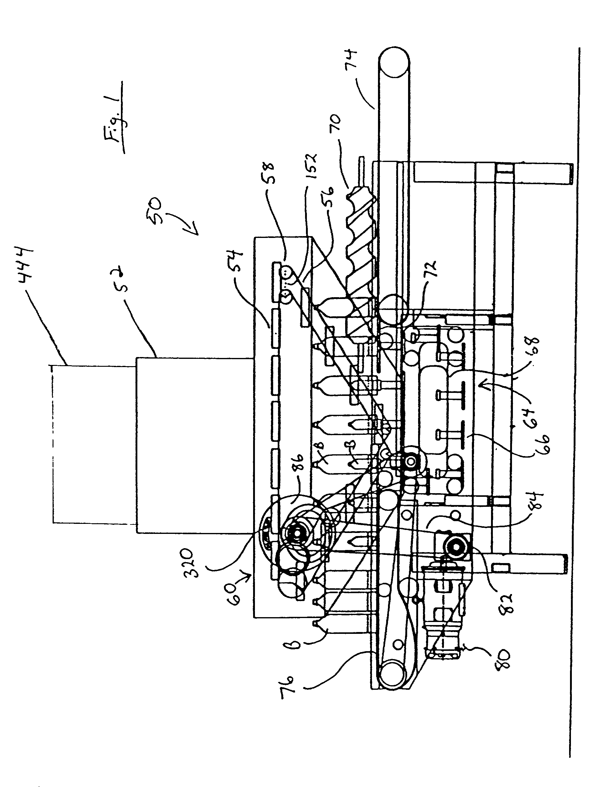
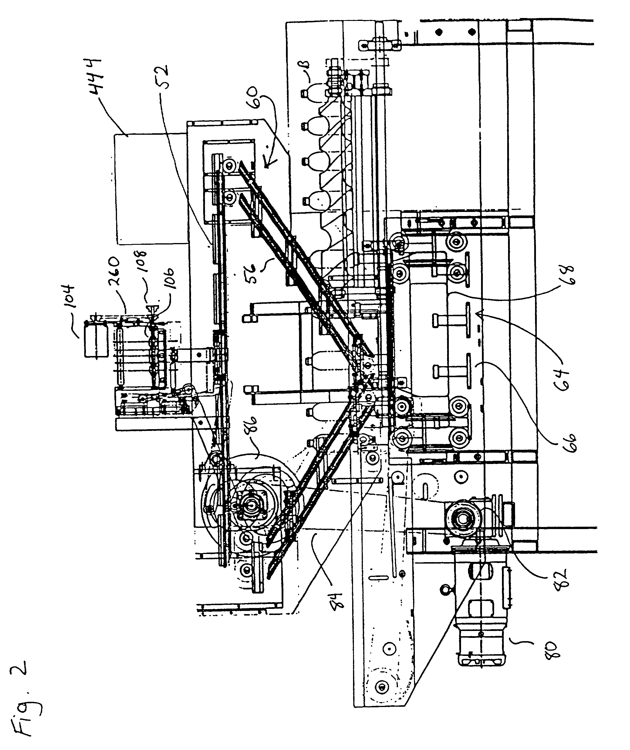
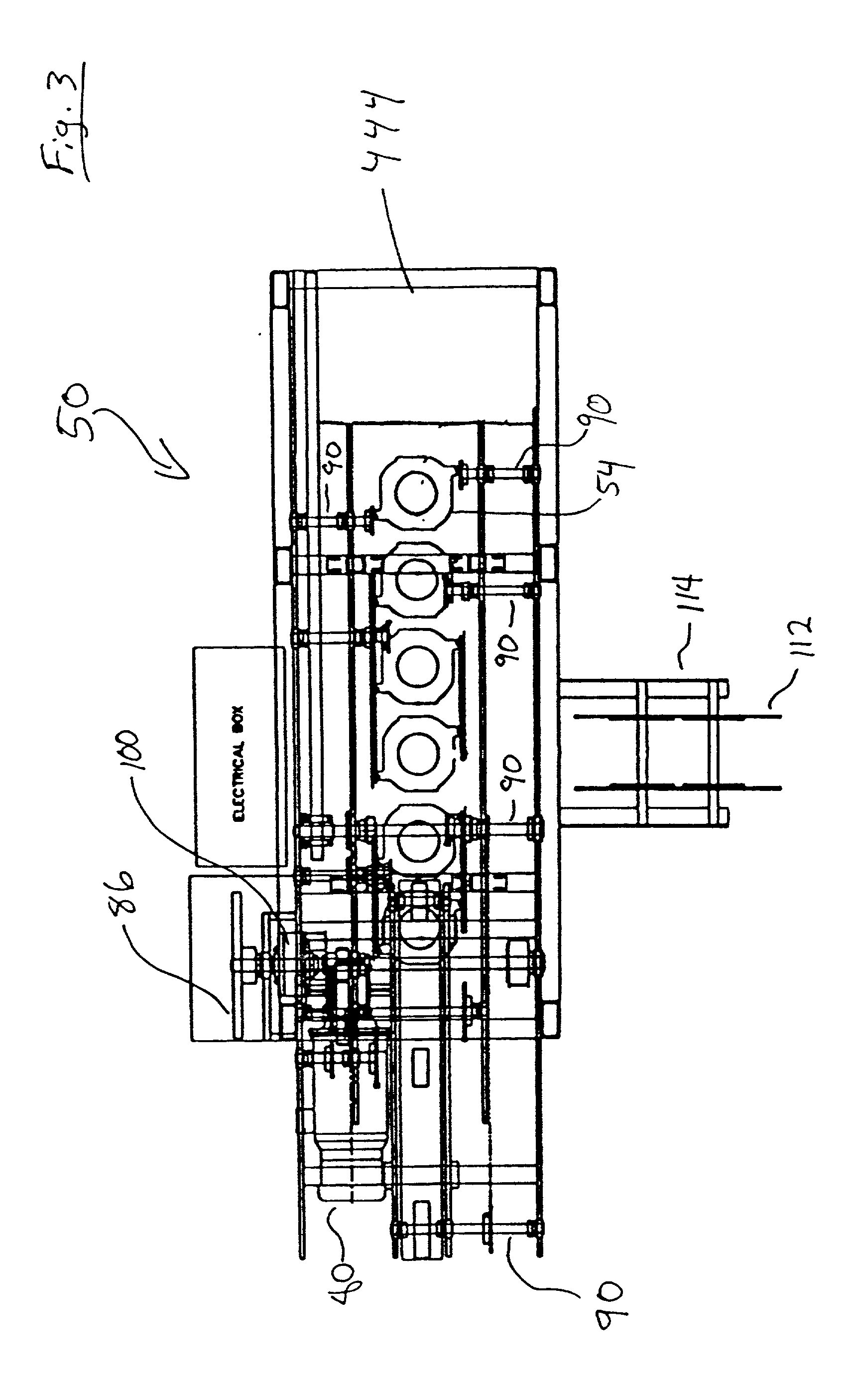
[0074] As shown in the Figures, the in-line continuous feed sleeve labeling machine 50 is shown generally in its entirety in FIGS. 1-6. The in-line continuous feed sleeve labeling machine 50 has the ability to sleeve or label bottles or containers continuously as they pass through the labeling machine 50. As used herein, the term "bot...


PUM

PropertyMeasurementUnit
frequenciesaaaaaaaaaa

Abstract

An in-line continuous feed sleeve labeling machine labels containers, such as beverage containers, in an in-line fashion maintaining the elevation of the containers during their linear transport. The in-line continuous feed sleeve labeling machine of the present invention receives bottles in flood feeder or linear fashion. A timing screw or the like properly separates, and both spatially and temporally disposes, the containers for sleeving. The timing screw propels the containers onto a pedestal system. The pedestals of the pedestal system maintain their horizontal nature due to offset pivotable attachments to the track system upon which they travel. A sheet of film is unspooled from an unwind roll and passed through a tube forming apparatus that overlaps the edges of the film. The overlapping edges completing the tube enclosure are connected using ultrasonic welding or the like. The sleeve is then passed to an iris carrier. In coordinated fashion with the travel of the pedestal system, iris carriers carrying sleeves upon articulating radial arms descend upon the bottles. Once the label sleeve has reached the appropriate point (generally adjacent to the central portion of the bottle), the iris carrier allows the label sleeve to engage the central portion of the bottle. Frictional attachment or otherwise allows the finger rods of the iris carrier to pull away from the sleeve as the iris carrier continues to descend down towards the pedestal. The sleeve then becomes attached to or engaged by the bottle until the finger rods of the iris carrier free themselves from the sleeve label. A container stabilizer may provide lateral bottle support and aid the ensleevement process. The finger rods then dilate to better disengage the bottle as the iris carrier ascends up and away from the bottle. The bottle is then transported to an exit conveyor having been properly sleeved, while the iris carrier returns to transport another sleeve.

Description

[0001] This application is a continuation-in-part of U.S. Utility patent application Ser. No. 09 / 295,549 incorporated herein by this reference.[0002] 1. Field of the Invention[0003] This invention relates to automatic labeling machines for bottles, containers, and the like, and more particularly to an in-line continuous sleeve or label applying machine that allows labels to be applied to the central portion of the bottle while the bottles remain in-line with the input and output bottle conveyors and a sleeve forming device using ultrasonic welding that allows sleeves to be formed contemporaneously with their application so that expensive tubular film need not be purchased in advance.[0004] 2. Description of the Related Art[0005] Container or bottle banding and sleeving have become more important in the recent past. Recent consumer concerns about health and safety issues regarding the intact and untampered nature of product purchases led manufacturers and suppliers to seal the tops o...

Claims


Application Information

Patent Timeline
Patent Type & Authority Applications(United States)
IPC IPC(8): B29C53/48B29C63/42B29C65/08B65C3/06
CPCB29C53/48B29C63/426B29C65/08B29C66/1122B29C66/43B65C3/065B29C65/00Y10T156/1705Y10T156/1744Y10T156/1768B29C66/4312B29C66/4322B29C66/49B29C66/5326
Inventor MENAYAN, VICTOR V.
Owner AXON LLC
Why Eureka
Try Eureka