

Wiring system of indication instrument for vehicle
a technology of indication instruments and wiring systems, applied in the direction of electrical devices, roofs, coupling device connections, etc., can solve the problems of heavy and expensive wiring systems, difficult connection work inside the indication instruments, and long time-consuming
- Summary
- Abstract
- Description
- Claims
- Application Information
AI Technical Summary
Benefits of technology
Problems solved by technology
Method used
Image

Examples
first embodiment
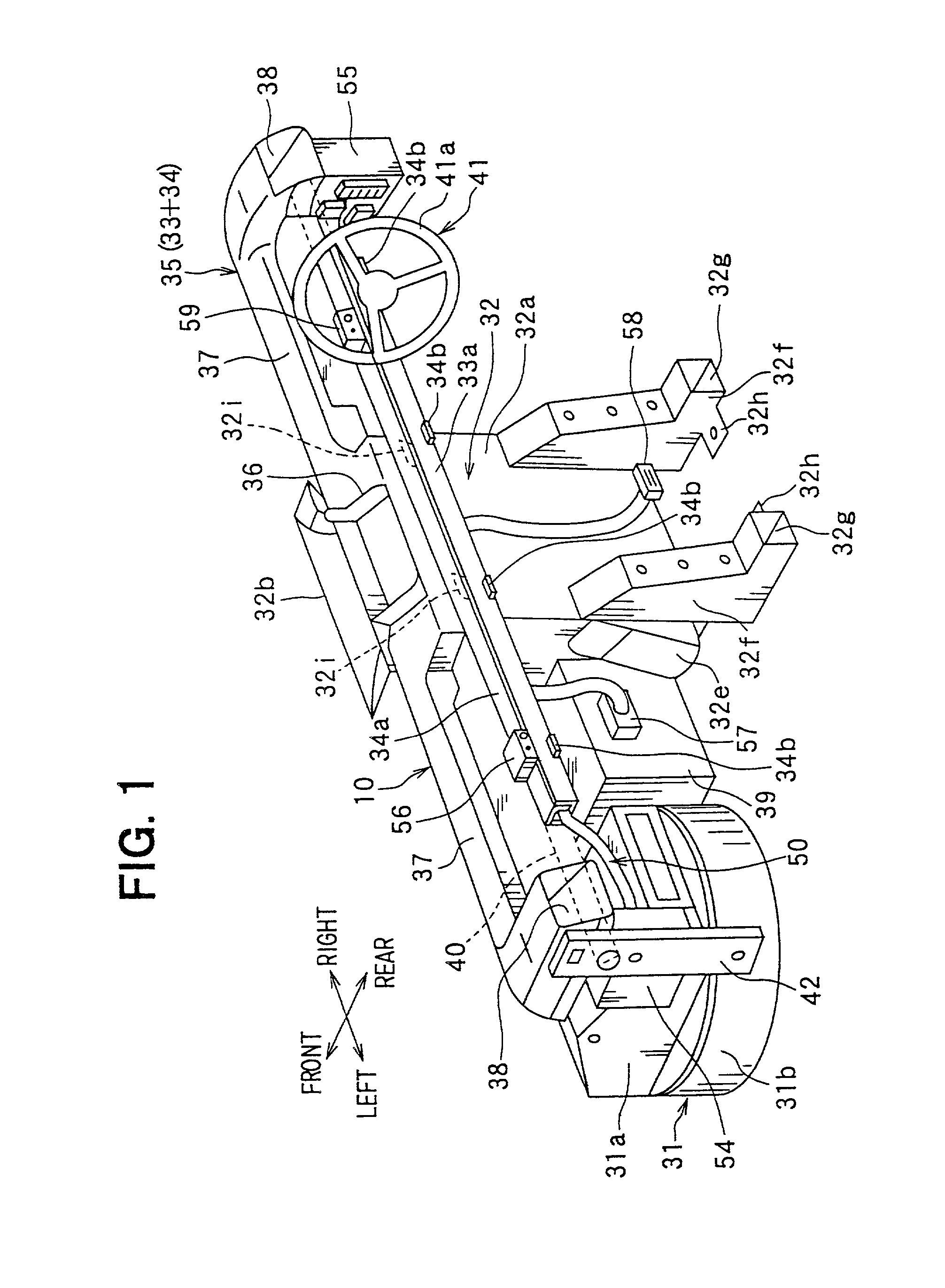
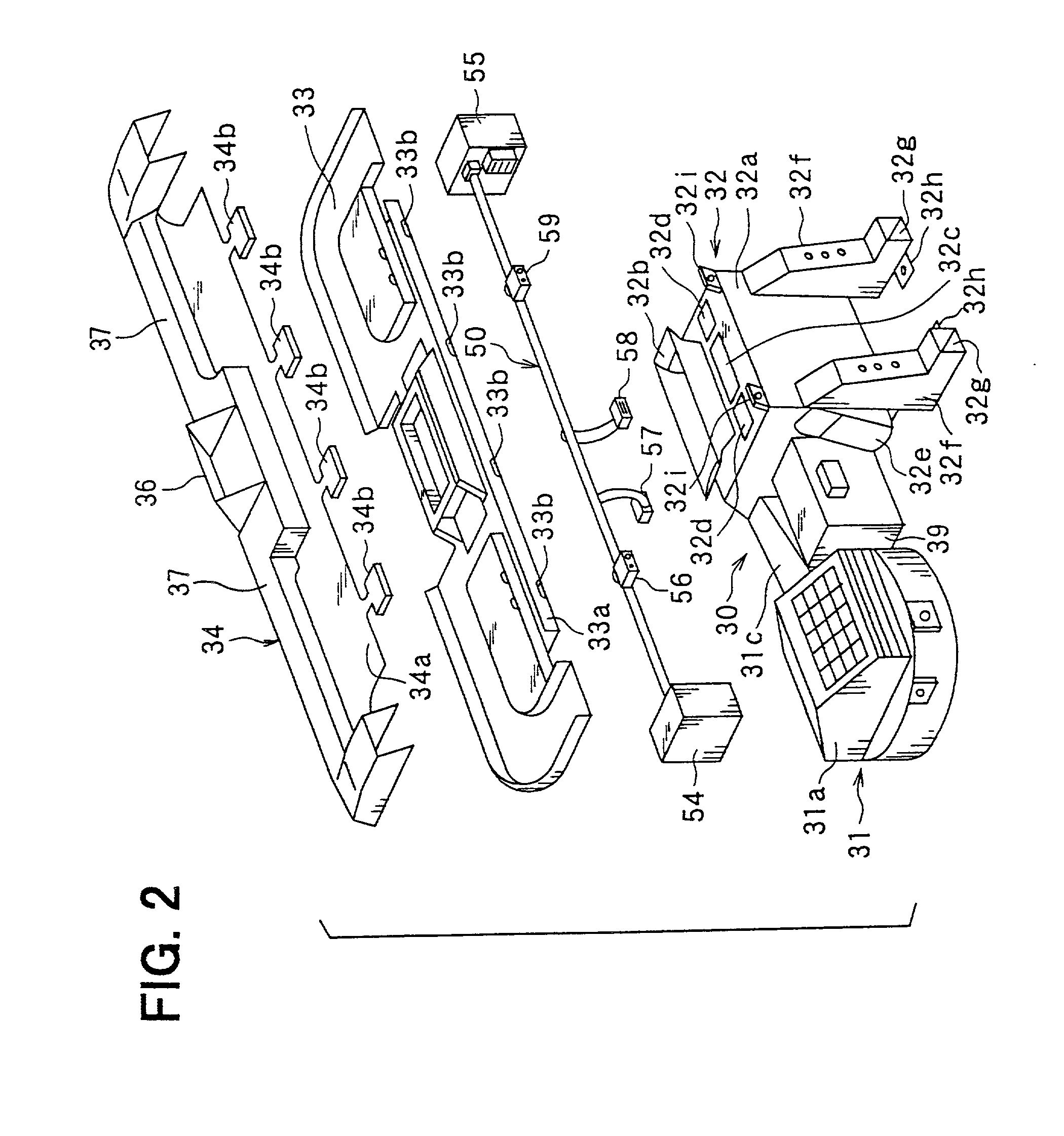
[0045] An indication instrument according to the invention is described with reference to FIGS. 1-4. Cockpit module 10 is disposed in vehicle indication instrument 20, which is illustrated in FIG. 4. Indication instrument 20 accommodates vehicle air conditioner 30, as shown in FIG. 2. In FIG. 1, crossing arrows indicate front-rear and right-left directions of the indication instrument mounted in a vehicle.
[0046] The word "cockpit module" used here includes not only an arrangement of indication instrument 20 that accommodates integrated devices but also various arrangements of indication instrument 20 that accommodates separately mounted devices.
[0047] Vehicle air conditioner 30 includes air blow unit 31 and air conditioning unit 32. Air conditioner 30 for a right-steering-wheel vehicle is shown here. Therefore, air blow unit 31 is disposed at the left passenger seat, and air conditioning unit 32 is disposed approximately at the center of the side-to-side direction of the vehicle.
[00...
second embodiment
[0091] An indication instrument according to the invention is described with reference to FIG. 5. Meter module 20b integrates therein a plurality of meters including a speedometer. Semi-cylindrical holder 33d is integrated with duct-base-plate 33 in front of gutter-shaped wire holder 33a. The upper outer periphery of pipe-shaped reinforcement bar 40 is fitted to semi-cylindrical holder 33d and fixed thereto by screw bolt 60. Thus, duct-base-plate 33 is fixed to reinforcement bar 40.
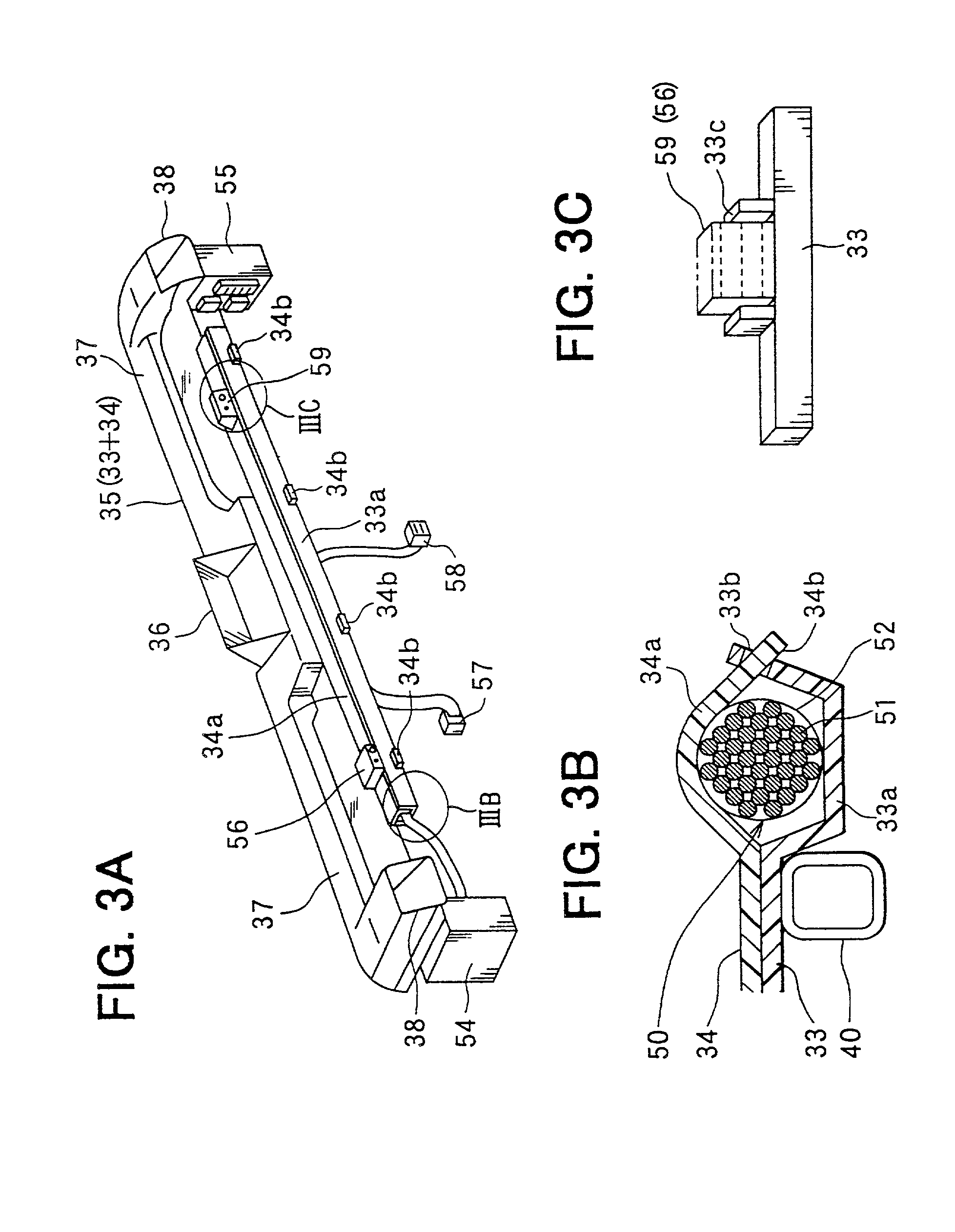
[0092] Support plate 33e extends upward from semi-cylindrical holder 33d of duct-base-plate 33. Support plate 33e penetrates wire fixing member 34a through a cutout of fixing member 34a. Wire 61 of the meter module branches from wire-integrated cluster 50. Wire 61 has connector 59 at its end, which is fixed at a portion of support plate 33e.
[0093] On the other hand, connector 62 is fixed to a portion of the back surface of meter module 20b. When meter module 20b is mounted in a prescribed portion of indic...
third embodiment
[0094] An indication instrument according to the invention is described with reference to FIG. 6. Reinforcement bar 40 is provided with distributor boxes 54 and 55 as side brackets, which are fixed to the right and the left ends of reinforcement bar 40.
[0095] Therefore, distributor boxes 54 and 55 are reinforced to have strength sufficient for reinforcement members. For example, material, thickness and a reinforcing member to be added are selected or designed.
[0096] Distributor boxes 54 and 55 have a plurality of fixing holes 64 for screw bolts or the like (not shown) so that the opposite ends of reinforcement bar 40 can be respectively fixed to the opposite sides of the vehicle body. Thus, distributor boxes 54 and 55 function as side brackets 42. It is also possible that the opposite sides of duct-base-plate 33 are fixed to left and right distributor boxes 54 and 55.
PUM
 Abstract
Description
Claims
Application Information