
Optical system for increasing contrast of object viewed through it

a technology of optical system and object, applied in the field of optical system for increasing contrast, can solve the problems of difficult to find the location of the ball and resume play, difficult to find the ball's position and resume play, and articles do little to help render the ball visible on the green or in other vegetation

Inactive Publication Date: 2001-06-28
YU CAROLINE
View PDF0 Cites 44 Cited by
  • Summary
  • Abstract
  • Description
  • Claims
  • Application Information

AI Technical Summary

Benefits of technology

[0013] It is a further object of the present invention to provide an optical system for locating a golf ball in a spotting scope, thereby better enabling the viewer to locate the object in its surroundings.
[0015] These objects and others that will become apparent from the following specification are achieved by providing an optical system having a selective optical wavelength filtering characteristic for increasing a contrast between a white object (i.e., a golf ball) and a vegetation (i.e., grass and / or forested) background. For example, the filter blocks green or green-yellow light wavelengths generally within the range of light wavelengths of about 500 to 600 nm. In addition, at least one polarizer or polarizing filter is provided for blocking glare which also serves to enhance color contrast.
[0016] Preferably, the optical system for increasing the contrast of an object viewed through it comprises in combination at least one lens, at least one polarizer, and a filter blocking light in the range of wavelengths of from about 450 to about 650 nm, i.e., a green or green-yellow blocking filter, such as, for example, a red, magenta, or blue pass filter. The filter preferably has a uniform optical retardance in order to avoid birefringent effects from the polarizer.
[0020] In different seasons, the vegetation may include differing predominant characteristic wavelengths. The optical filters may therefore be changed or adjusted for maximum contrast for the particular conditions. It has been found that, although a magenta (pass) filter is advantageous when the vegetation is lush, when the vegetation is wooded or is subjected to dry conditions, a blue (pass) filter may be preferred. A significant factor in the success of the filter is that sufficient contrast be maintained. To this end, it is preferable to have a pass band that transmits a relatively large fraction of light, (i.e., about 90% or greater transmittance) while having a stop band that transmits a small fraction of light (i.e., approximately zero transmittance). For example, a pass band to stop band ratio of the optical filter of at least about 4 is preferred. In other words, a greater differential between the light transmittance in the pass band to stop band is preferred to provide the greatest contrast.
[0027] In contrast to normal sunglasses, the optical filtering according to the present invention typically provides a wider separation between the optical pass band and stop band. Since the typical object to be seen is a bright white (golf ball), the amount of attenuation in the pass band is less critical than the difference in attenuation between the pass band and stop band.

Problems solved by technology

Golf courses typically have challenging terrain which makes this feat difficult, including various twists and turns in terrain, interrupted by various obstacles such as trees, sand traps, and the like.
When this happens, it is often difficult to find the location of the ball and resume play.
Although sunglasses and hats bearing visors generally assist in reducing glare from sunlight, these articles do little to help render the ball visible on the green or in other vegetation.
Furthermore, magnifying devices may assist in improving distance viewing but provide little or no assistance in providing contrast between the ball and its surroundings.
Although known lens designs provide enhanced perception of certain colors, they do not solve the problems faced by a golfer in locating a lost golf ball.

Method used


Image

  • Optical system for increasing contrast of object viewed through it
  • Optical system for increasing contrast of object viewed through it
  • Optical system for increasing contrast of object viewed through it

Examples


Embodiment Construction

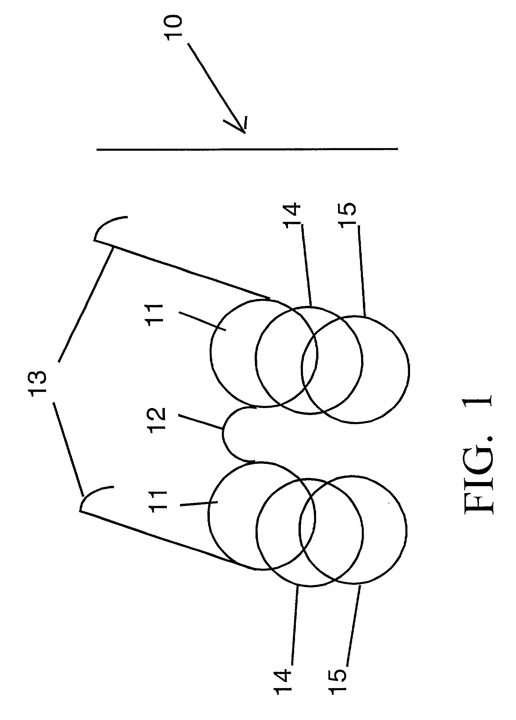
[0035] FIG. 1 illustrates one embodiment of the optical system 10 of the invention (everything to the left of the vertical line indicated by "10"). Corrective or plano lenses 11 are set in an eyeglass frame 12, which has side frames 13. In front of lenses 11 are at least one pair of filters 14 with no more than about 20% transmittance of light in the range of wavelengths of from about 500 nm to 700 nm. Preferably, the pair of filters 14 substantially blocks light in the range of wavelengths of from about 500 nm to about 620 nm. In front of the filters 14 are at least one pair of polarizers 15. The filters 14 and polarizers 15 may be made to clip-on the glasses. When the intended user does not wear corrective lenses, 11 represents openings in the frame in which filters 14 and polarizers 15 may be mounted.

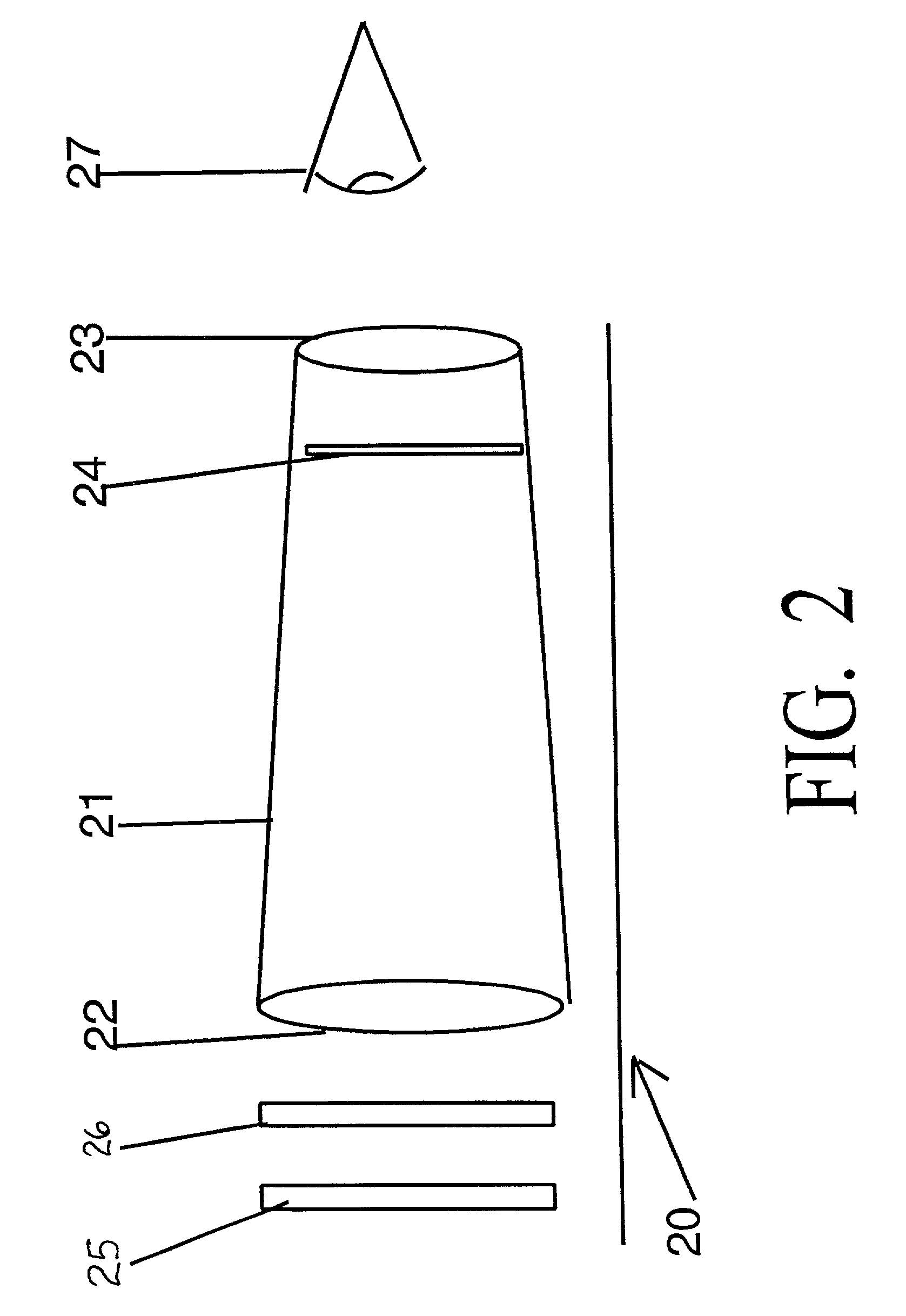
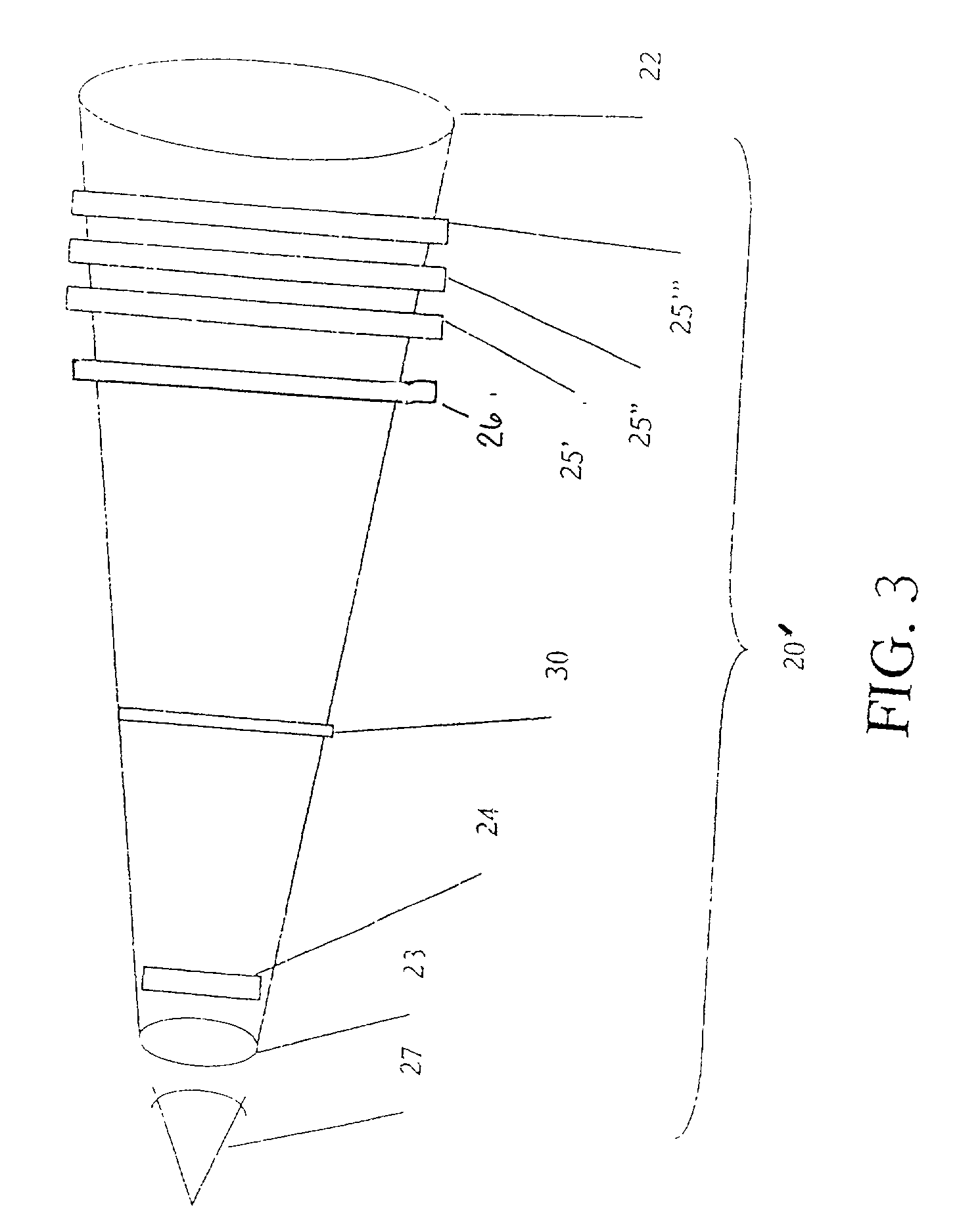
[0036] FIG. 2 illustrates another embodiment of the optical system 20 of the present invention (everything above the horizontal line indicated by "20"). A spotting scope 21 has an ob...


PUM


Abstract

An optical system for providing a viewer with contrast between a golf ball and its environment, including a light filter and at least one polarizer mounted in a viewing device. The light filter has no more than about 20% transmittance of light in one of the range of wavelengths of from about 500 nm to about 700 nm. The viewing device allows for the light filter and the polarizer to be arranged in front of at least one eye of the viewer. The optical system can be provided in a spotting scope, a pair of eyeglasses or an attachment to eyeglasses for ease of use.

Description

[0001] 1. Field of the Invention[0002] The present invention relates to an optical system for increasing the contrast of an object viewed through it, thereby enabling the viewer to selectively locate the object in its surroundings. Especially advantageous is the incorporation of a spotting scope or monocular as part of the optical system in order to provide magnification and create a greater contrast between a golf ball (generally white) and its golf course environment. This contrast helps the user find his or her golf ball more easily.[0003] 2. Description of the Related Art[0004] Recreational golf is a popular sport in which the golfer attempts to hit a small, usually white golf ball into a distant hole. Golf courses typically have challenging terrain which makes this feat difficult, including various twists and turns in terrain, interrupted by various obstacles such as trees, sand traps, and the like. More often than desired, a golfer who has intended to hit a ball, for example s...

Claims


Application Information

Patent Timeline
IPC IPC(8): G02B23/00G02B27/28G02C7/10G02C7/12
CPCG02B23/00G02B27/28G02B27/281G02C7/12G02C7/104
Inventor YU, CAROLINE
Owner YU CAROLINE
Learn More