
Impulse motor and apparatus to improve trajectory correctable munitions including cannon launched munitions, glide bombs, missiles, rockets and the like

Inactive Publication Date: 2001-08-23
LINICK JAMES M
View PDF0 Cites 2 Cited by
  • Summary
  • Abstract
  • Description
  • Claims
  • Application Information

AI Technical Summary

Benefits of technology

[0017] It is an object of the invention to affect the necessary munition(s) correction while in-flight, resulting in increased accuracy and utilization of a minimum of internal munitions volume.
[0018] It is another object of the invention to decrease the volume occupied by the trajectory correction means and apparatus, and subsequently increase the volume available for on board lethal cargo payload of all sorts, thereby offering increased accuracy together with substantially increased lethality.
[0019] It is another object of the invention as further described herein to utilize the vastly increased power of deflagration or detonation materials, while maintaining impulse control, without destroying the munition whose trajectory is being corrected, and without increasing the trajectory correctable munition(s) cost or complexity.
[0020] It is another object of the invention to create trajectory correctable munitions whose trajectory correction means utilize substantially less internal munitions volume than munitions corrected with ordinary propellants as described in the example in the Background of the Invention, with the result being substantially increased lethality on target with no increased cost, while still providing at least a 50% to 95% improved cost to kill ratio, and a vastly decreased logistical tail because less munitions, guns, personnel and other military equipment will be required to accomplish the same mission without the benefits provided by this invention.

Problems solved by technology

However, a fairly stable platform is essential for this method, and a spinning platform would make in flight direct control via this method extremely difficult.
Further, such control surfaces often have a limited effect in the thin ambient air encountered at high altitudes.
However, one drawback is the size of the containment apparatus and the reactive structures and other required apparatus to support such deflagration materials, with their massive forces of expansion.
Such drawbacks may very well outweigh the obvious benefits of deflagration materials.
However, the use of deflagration and detonation materials is difficult to control and may very well destroy the munition in-flight rather than correct the trajectory of such flights.

Method used


Image

  • Impulse motor and apparatus to improve trajectory correctable munitions including cannon launched munitions, glide bombs, missiles, rockets and the like
  • Impulse motor and apparatus to improve trajectory correctable munitions including cannon launched munitions, glide bombs, missiles, rockets and the like

Examples


Embodiment Construction

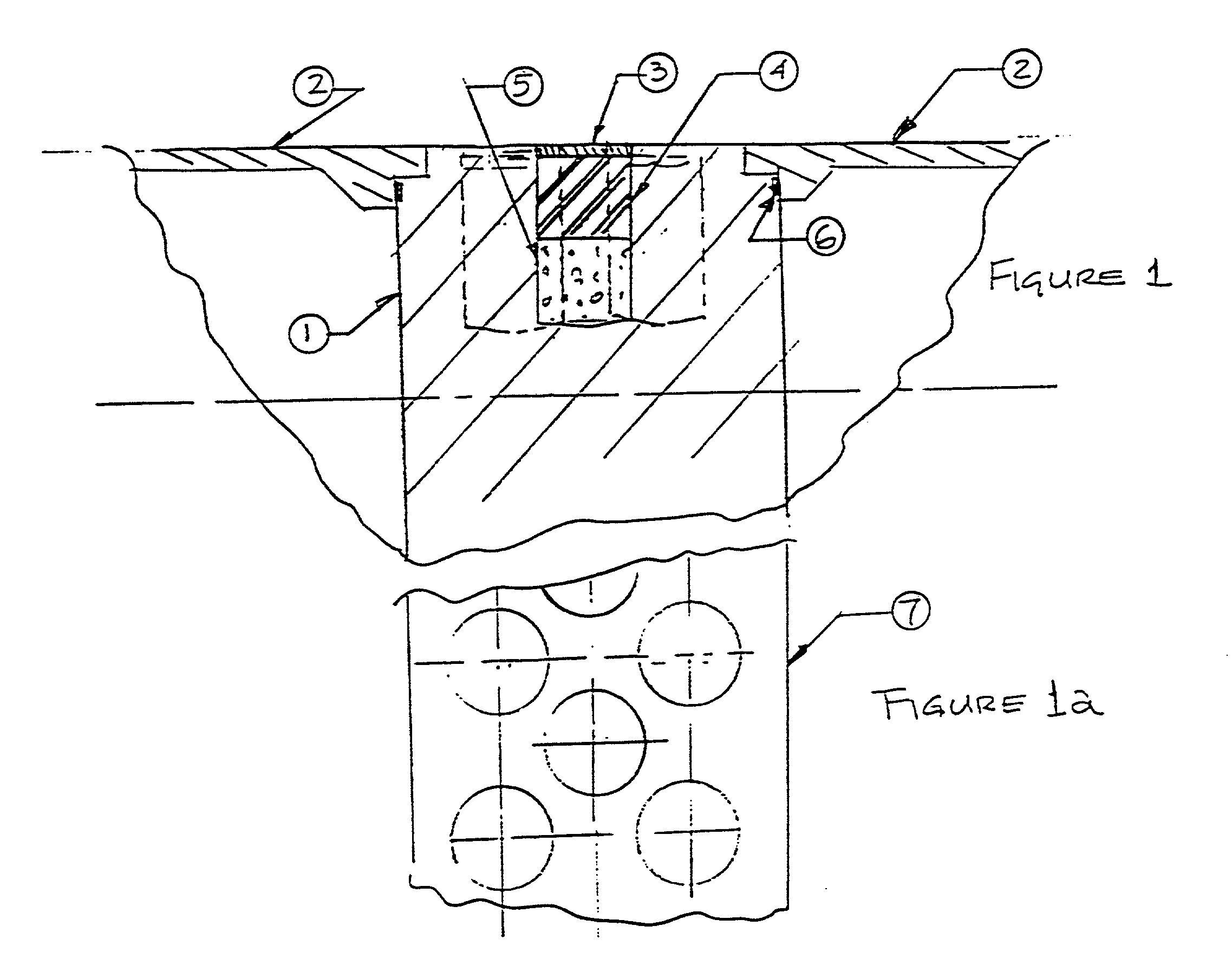
[0029] FIG. 1 illustrates one preferred embodiment of the invention. An impulse motor assembly body 1 is located within the motor housing 2 of a munition. The impulse motor assembly body 1 includes a slug 4, a slug conformal cap 3, and a propellant 5 for propelling the slug 4 outward and away from the munition. The assembly body 1 is made of a strong material with some degree of malleability, such as any number of steel alloys or titanium alloys. In one embodiment, the material used in the barrel of a firearm is used. The slug may be made of a heavy metal, and in one preferred embodiment, such slugs 4 could be depleted uranium (DU) having an exponentially greater reactive mass than the reactive mass of the expanding gas alone. The slug conformal cap 3 serves to environmentally seal the slugs 4, as well as ensure an aerodynamic and conformal exterior shape for the munition(s) body. The propellant 5 may be a compressed gas, a deflagration material, a detonation material, or some other...


PUM


Abstract

An device for correcting the in-flight trajectory of a munition consists of an impulse motor assembly body. The slug or multiple slugs and propellant(s) are located within the impulse motor assembly body. When a trajectory correction is desired and required, the individual impulse motor propellants are activated and fired, and the slug or multiple slugs are propelled out of the in-flight munition at a specific time and a specific angle on or near the gravimetric center of gravity of the in-flight munition. The reactive forces created by the explosion of the(se) heavy metal slugs does, by equal and opposite reaction, create a corrective vector and thereby does cause a correction in the trajectory of the in-flight munition.

Description

[0001] This invention is related to the field of munitions, and more particularly toward in-flight corrections of these munitions.[0002] There are known methods of correcting the trajectory of in-flight munitions. One such method is described in U.S. Pat. No. 5,131,602, entitled "Apparatus for Remote Guidance of Cannon-Launched Projectiles." Another method is described in U.S. Pat. No. 5,647,558, entitled "Method and Apparatus for Radial Thrust Trajectory Correction of a Ballistic Projectile," issued to the present inventor.[0003] One known method of correcting the trajectory of munitions in-flight is with aerodynamic control surfaces. However, a fairly stable platform is essential for this method, and a spinning platform would make in flight direct control via this method extremely difficult. Further, such control surfaces often have a limited effect in the thin ambient air encountered at high altitudes.[0004] Another known method uses impulse motors or rockets, usually acting near...

Claims


Application Information

Patent Timeline
IPC IPC(8): F41G7/30
CPCF41G7/305F42B10/661
Inventor LINICK, JAMES M.
Owner LINICK JAMES M
Learn More