
Optical low pass filter

a filter and optical low-pass technology, applied in the field of optical low-pass filters, can solve the problems of difficult to minimize the optical low-pass filter of the solid-state image sensor of the square grid structure cannot efficiently suppress the aliasing noise, and the optical low-pass filter cannot be efficiently suppressed

Inactive Publication Date: 2001-08-30
FUJIFILM CORP
View PDF0 Cites 10 Cited by
  • Summary
  • Abstract
  • Description
  • Claims
  • Application Information

AI Technical Summary

Problems solved by technology

According to the sampling theorem, higher frequency components than a Nyquist rate, that is one half of a spatial frequency determined by the pitch of arrangement of the pixels, cause the aliasing noise.
Because the ideal frequency characteristics of the optical low-pass filter for the solid-state image sensor of the offset sampling structure are different from those for the solid-state image sensor of the square grid structure, the optical low-pass filter for the solid-state image sensor of the square grid structure cannot efficiently suppress the aliasing noise.
Since the conventional optical low-pass filter such as disclosed in the above mentioned prior arts needs three birefringent plates, it has been difficult to minimize the optical low-pass filter, and the conventional optical low-pass filter is relatively expensive.

Method used


Image

  • Optical low pass filter
  • Optical low pass filter
  • Optical low pass filter

Examples


Embodiment Construction

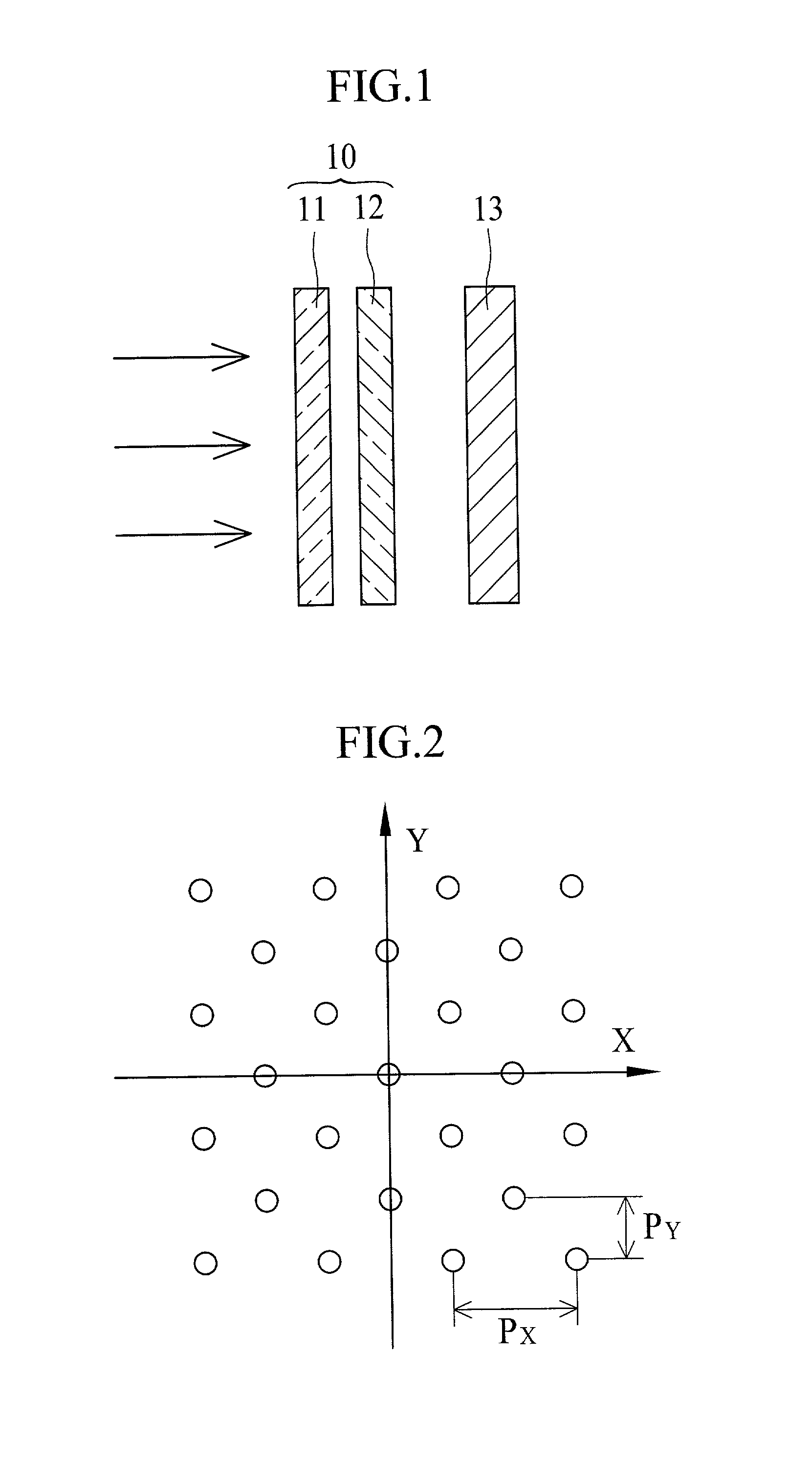
[0036] FIG. 1 shows a configuration of an optical low-pass filter 10 of the present invention. The optical low-pass filter 10 consists of first and second optical members 11 and 12 arranged in this order from the object side in front of a solid-state image sensor 13. The solid-state image sensor 13 has an offset sampling structure like as shown in FIG. 2, wherein X-axis corresponds to a horizontal scanning direction of the solid-state image sensor 13, and Y-axis corresponds to a vertical direction. In the present embodiment, the pitch Px of pixels of the solid-state image sensor 13 in the horizontal scanning direction is twice the pitch Py in the vertical direction: Px=2.multidot.Py. In the following description, splitting angles of the optical low-pass filter will be defined with respect to the horizontal scanning direction.

[0037] The optical members 11 and 12 are formed by cutting a birefringent material, such as rock crystal, lithium niobate, in predetermined directions. As shown...


PUM


Abstract

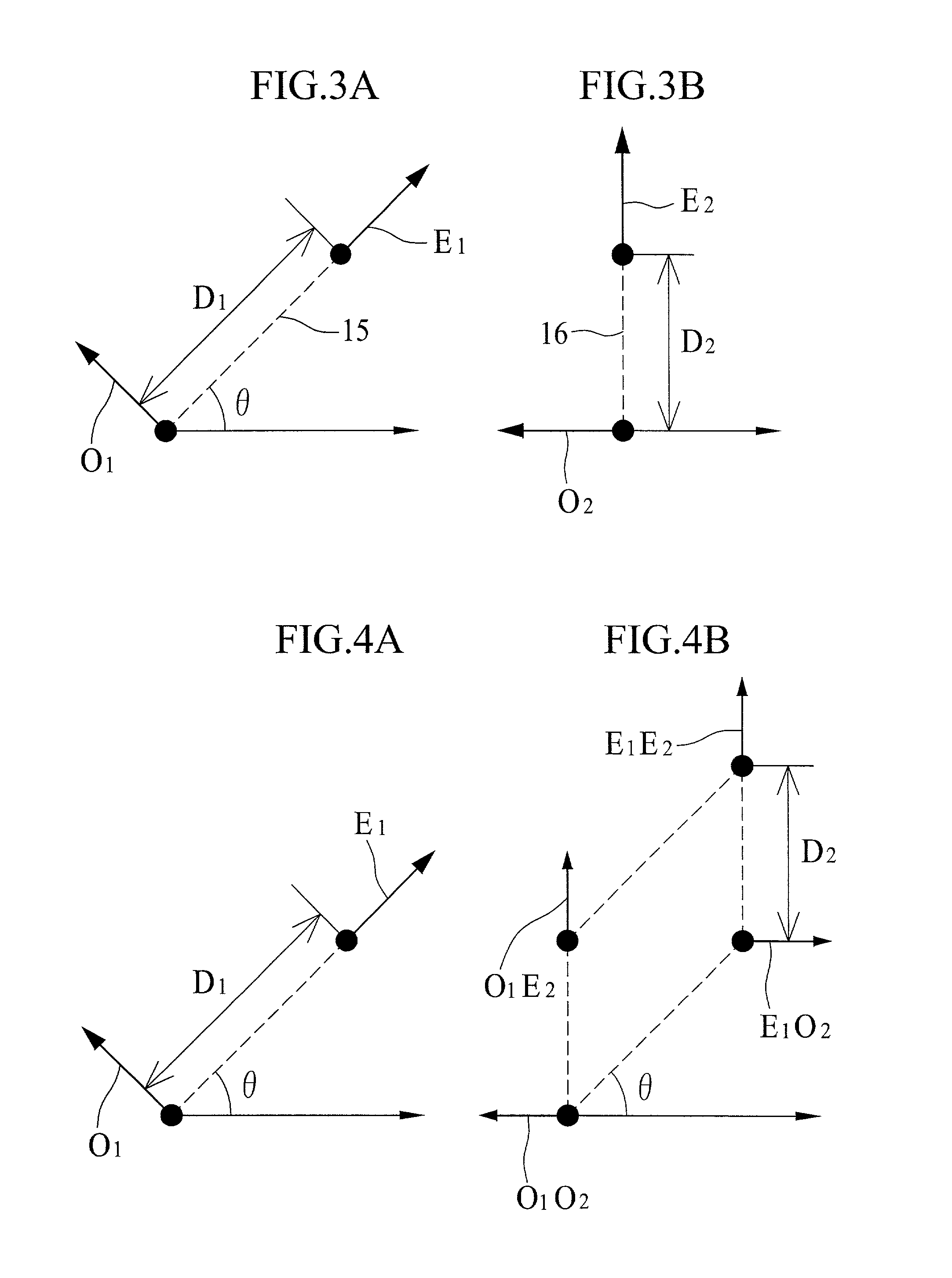
An optical low-pass filter for a solid-state image sensor of an offset sampling structure is constituted of first and second optical members. The first optical member splits an incident light ray into a rectilinear ray and a refracted ray whose propagation direction is about 45° to a horizontal direction of the solid-state image sensor. The second optical member splits an incident ray into a rectilinear ray and a refracted ray whose propagation direction is about 90° to the horizontal direction. The optical low-pass filter having this configuration splits the incident light ray into four rays whose split points are at respective corners of a parallelogram. Assuming that Px represents a sampling interval in the horizontal direction, Py represents a sampling interval in the vertical direction, and D1 and D2 represent respective split widths of the incident light rays through the first and second optical members, the split widths D1 and D2 satisfy the following conditions: D1≈Px / {square root}{square root over ( )}2 and Py<=D2<=2.Py.

Description

[0001] 1. Field of the Invention[0002] The present invention relates to an optical low-pass filter that is placed in front of a solid state image sensor having an offset sampling structure, for eliminating high-frequency components from incident light.[0003] 2. Background Arts[0004] The solid-state image sensor has an array of photo sensor cells, called pixels, for obtaining an image signal through discrete sampling and photoelectric conversion of an optical image of a subject. According to the sampling theorem, higher frequency components than a Nyquist rate, that is one half of a spatial frequency determined by the pitch of arrangement of the pixels, cause the aliasing noise. Since the aliasing noise appears in the form of spurious signal or moire, it is necessary to eliminate the higher frequency components prior to the sampling. For this purpose, an optical low-pass filter is placed in front of the solid-state image sensor in an imaging apparatus.[0005] As the optical low-pass f...

Claims


Application Information

Patent Timeline
IPC IPC(8): G02B5/18G02B5/30G02B27/46H01L27/14H04N5/335H04N5/357H04N5/369
CPCG02B5/3083
Inventor TAMARU, MASAYAODA, KAZUYAMISAWA, TAKESHIKAYANUMA, YASUNOBUORIMOTO, MASAAKI
Owner FUJIFILM CORP
Learn More