Drum brake device

a technology of drum brake and rotor, which is applied in the direction of mechanically actuated drum brakes, fluid actuated drum brakes, mechanical apparatus, etc., can solve the problems of unstable braking force, premature wear down of abutment surfaces, and drawbacks and deficiencies of the above-described prior art, so as to improve the driver's braking feeling, prevent wear and deformation of the pivot section, and improve the effect of brake efficiency

Inactive Publication Date: 2001-09-06
NISSHINBO IND INC
View PDF0 Cites 3 Cited by
  • Summary
  • Abstract
  • Description
  • Claims
  • Application Information

AI Technical Summary

Benefits of technology

0012] It is an object of this invention to improve brake efficiency, prevent wearing and deformation of the pivot section of the brake

Problems solved by technology

The above-described prior art suffers from following drawbacks and deficiencies.
Since the adjacent ends g.sub.1, h.sub.1 and g.sub.2, h.sub.2 of the pivot levers g, h slidably move on the pistons k, m and the anchors, e, f during the brake operation, the prior art produces problems by creating sliding resistance between the ends of the pivot levers g, h and the pistons k, m or the anchors e, f causes an unstable braking forc

Method used


Image

  • Drum brake device
  • Drum brake device
  • Drum brake device

Examples


embodiment 1

[0037] Embodiment 1

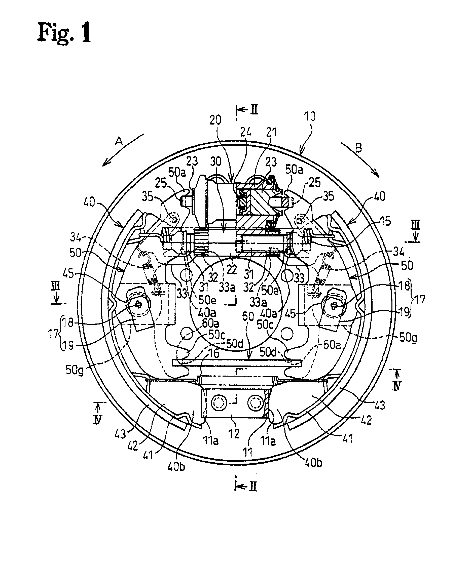
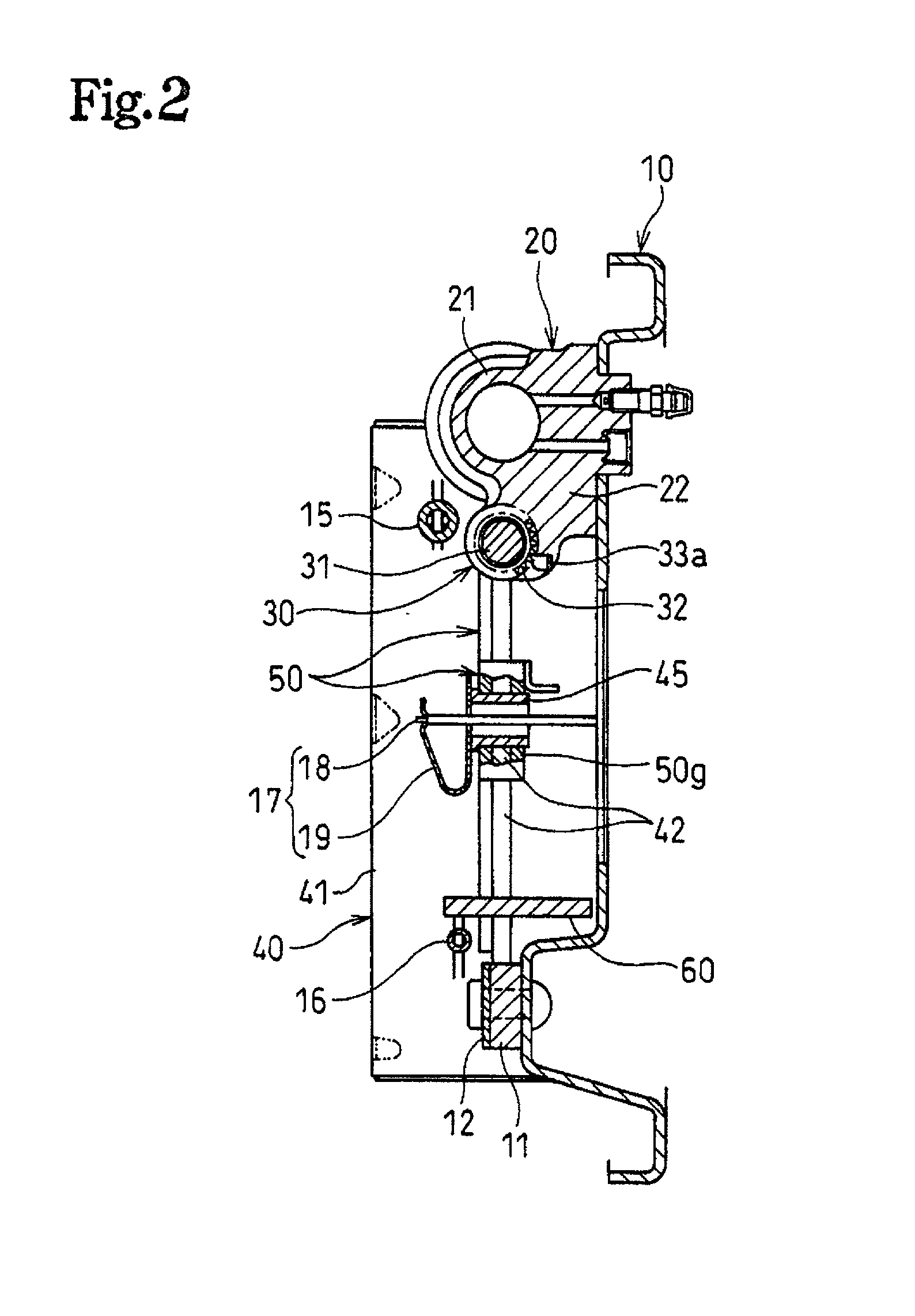
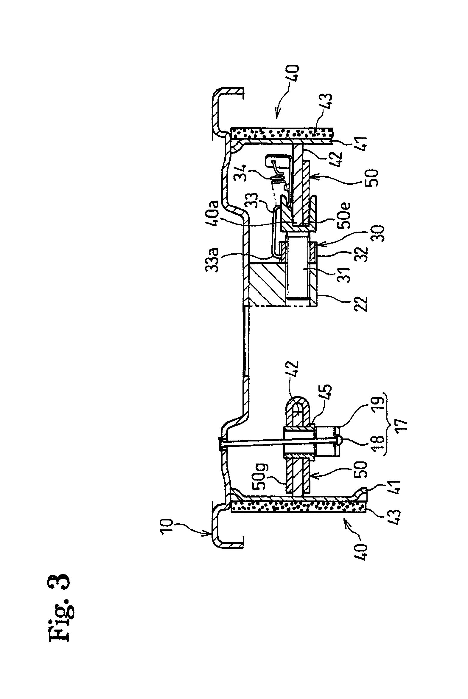
[0038] A first embodiment of a drum brake device in this invention is explained with reference to FIGS. 1-10. Since the structure of this drum brake device is such that the right half and the left half of the drum brake in FIGS. 1-10 are symmetrically structured, the following explanation illustrates only one half of the figures while the explanation of the other half is omitted by utilizing the same reference numbers for both halves of the device. The terms "right" or "left" and "upper" or "lower" are used for clarification when explaining applicable devices; however, the direction of the drum brake device set is not limited to that which is illustrated in the figures.

[0039] As shown in FIG. 1, a hydraulic cylinder 20 functioning as a service brake actuator is mounted on a back plate 10, fixed on a non-rotatable part of a vehicle. A piston 23 is strokably housed inside a cylinder body 21 of the hydraulic cylinder 20.

[0040] Utilizing an anchor body 22 integrally f...


PUM


Abstract

An object of this invention is to improve brake efficiency, to prevent wear down and deformation of the pivot section between the brake shoe and the pivot lever, and to improve the operator's comfort level during braking. For those purposes, this invention is to provide a drum brake device, wherein a supporting device for supporting the adjacent ends of the pivot levers is such that the pivot levers may easily follow the brake shoe movement in the drum's rotational direction.

Description

[0001] 1. Field of the Invention[0002] This invention relates to a drum brake device and particularly to a drum brake device having pivot levers that follow brake shoe movement in the brake drum's rotational movement.[0003] 2. Description of the Related Art[0004] Japanese Laid Open Patent Application No. 10-47296 discloses a drum brake device attaining a stable braking force just like a dual two leading (hereinafter D2L) type drum brake device despite use of only one service brake actuator (i.e., hydraulic cylinder).[0005] A prior art drum brake device is explained with reference to FIG. 18. The drum brake device includes the following: two anchors c, d that are positioned between facing adjacent ends a.sub.1, b.sub.1 of a pair of brake shoes a, b; shoe clearance adjustment devices e, f also functioning as anchors are similarly positioned between the other adjacent ends a.sub.2, b.sub.2 of the brake shoes a, b; pivot levers g, h are rotatably pivoted under central regions of the bra...

Claims


Application Information

Patent Timeline
IPC IPC(8): F16D51/24F16D51/30F16D51/50F16D65/09F16D65/14F16D65/22F16D65/46F16D65/56
CPCF16D51/24F16D51/50F16D65/22F16D65/46F16D65/565F16D2121/02F16D2121/14F16D2123/00F16D2125/64F16D2125/66F16D65/09
Inventor HASEGAWA, JUNICHI
Owner NISSHINBO IND INC
Why Eureka
Try Eureka