Stage device capable of moving an object to be positioned precisely to a target position

Inactive Publication Date: 2001-09-06
SHARP KK
View PDF0 Cites 16 Cited by
  • Summary
  • Abstract
  • Description
  • Claims
  • Application Information

AI Technical Summary

Benefits of technology

0011] Accordingly, an object of the present invention is to provide a stage device which can prevent deflection of an object to be positioned and a stage in a yawing or pitching direction due to displacement of the centroid position thereof when the object to

Problems solved by technology

In a conventional stage device, however, when an object to be positioned is moved in one of two directions perpendicular to each other and then moved in the other remaining direction, the object to be positioned may not be positioned in the driving center of a drive mechanism (central position between the linear motors when

Method used


Image

  • Stage device capable of moving an object to be positioned precisely to a target position
  • Stage device capable of moving an object to be positioned precisely to a target position
  • Stage device capable of moving an object to be positioned precisely to a target position

Examples


Example

[0056] The present invention is described in detail below with reference to embodiments shown in the drawings.

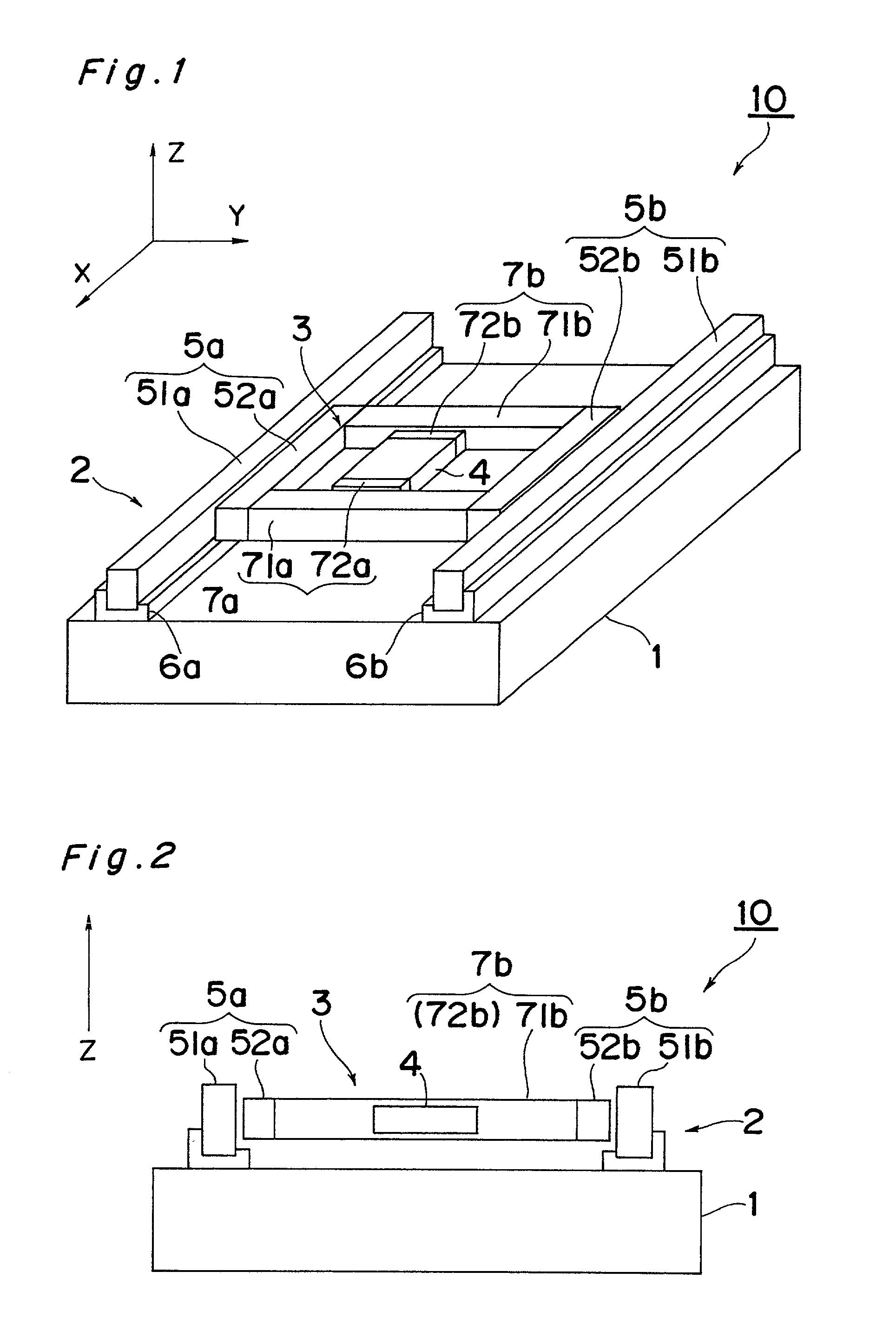
[0057] FIG. 1 is an external view showing a constitution of a stage device according to an embodiment of the invention. A stage device 10 is applied to an aligner in use for a lithography process, in which a mask pattern is transferred to a substrate such as a wafer or the like, in manufacture of a semiconductor element, liquid crystal display element, thin film magnetic head or the like. A wafer is moved to an arbitrary target position in a predetermined range in an X direction and a Y direction perpendicular to each other. This stage device 10 is constituted by an X-direction stage 2 constituted on a top surface of a vibration isolating table 1, a Y-direction stage 3 provided movably in the X direction on the X-direction stage 2 and a wafer stage 4 provided movably in the Y direction perpendicular to the X direction on the Y- direction stage 3.

[0058] The vibration isolatin...


PUM


Abstract

In a state that a wafer stage is not positioned in the center of the Y-direction traveling range, thrusts Fa, Fb supplied from a pair of linear motors to a Y-direction stage are made different and the Y-direction stage is moved in the X direction so that moments Ma, Mb about the centroid of the Y-direction stage by the thrusts Fa, Fb cancel each other. Since the moments Ma, Mb about the centroid generated by the thrusts cancel each other and the thrusts do not act as forces for rotating the Y-direction stage, the Y-direction stage is not deflected in a yawing direction. Such a stage device as constructed above can prevent deflection in a yawing direction due to displacement of the centroid position of an object to be positioned or a stage and precisely move the object to be positioned to a target position.

Description

[0001] The present invention relates to a stage device which is used in an aligner used in a lithography process in manufacture of a semiconductor element or the like, a machine tool used for machining of works and a precision mechanical equipment such as a measuring device or the like for measuring a shape of an object to be measured and moves an object to be positioned such as a work or the like to a target position.[0002] As a device for moving an object to be positioned to a target position, for example, an aligner for use in a lithography process, in which a mask pattern is transferred onto a substrate such as a wafer or the like, in manufacture of a semiconductor element, liquid crystal display element, thin film magnetic head or the like needs to precisely position the wafer, which is an object to be positioned, to a predetermined exposure position. Therefore, the aligner is provided with a wafer stage on which a wafer is mounted and a stage device having a travel mechanism f...

Claims


Application Information

Patent Timeline
IPC IPC(8): G03F7/20
CPCG03F7/70716G03F7/70725G03F7/70766
Inventor SAWAI, HIROYUKIISHII, HIROSHI
Owner SHARP KK
Why Eureka
Try Eureka