Coordinate-capturing apparatus

a technology of coordinate capture and input pen, which is applied in the direction of instruments, cathode-ray tube indicators, computing, etc., can solve the problems of increasing manufacturing costs, difficult to carry out position determination, and so as to shorten the sampling period and shorten the emission period of electromagnetic signals , the effect of large power consumption in the input pen

Inactive Publication Date: 2001-09-13
OKI DATA CORP
View PDF14 Cites 32 Cited by
  • Summary
  • Abstract
  • Description
  • Claims
  • Application Information

AI Technical Summary

Benefits of technology

0006] In the 2-ultrasonic-wave+electromagnetic-wave type, to obtain a smooth curve of detected coordinates even when the pen moves fast, it is necessary to shorten a sampling period, that is, to shorten the period of emission of the electromagnetic signal from the pen. Besides, since electric power drawn for emitting ultrasonic signals is large, power consumption in the input pen is large and therefore a battery included in the pen is short-lived.
0007] An object of the present invention is to make it possible to perform coordinate detection smoothly even when the input pen moves fast.
0008] Another object of the present invention is to reduce electric power consumption in the input pen to increase the life-span of a battery included in the input pen.

Problems solved by technology

The above 3-ultrasonic-wave type has a problem that the determination of the position of the sounding object is greatly affected by the accuracy of positioning the three microphones, and therefore it is difficult to carry out the position-determination, with high precision and high accuracy.
In addition, since it is unknown at which microphone the ultrasonic signal arrives first, it is necessary to watch for the ultrasonic signal by the three microphones continuously, which requires a complicated circuit structure to perform complicated calculations, and therefore increases the cost of manufacturing.
Besides, since electric power drawn for emitting ultrasonic signals is large, power consumption in the input pen is large and therefore a battery included in the pen is short-lived.

Method used


Image

  • Coordinate-capturing apparatus
  • Coordinate-capturing apparatus
  • Coordinate-capturing apparatus

Examples


first embodiment

[0074] As described above, in the first embodiment, a time period (pulse period) between receiving a pulse in a pulse train of the ultrasonic signal and receiving the succeeding pulse is clocked, and this clocked time period is multiplied by the ratio (a predetermined value: h) of the period of the ultrasonic pulse train to the pulse period to determined the time elapsed between emission of a pulse train of the ultrasonic signal and emission of the succeeding pulse train at the ultrasonic oscillator 3.

[0075] In the first embodiment, the period of emission of the light signal is longer than the period of emission of the ultrasonic signal. The ratio j of the period of emission of the light signal to the period of emission of the ultrasonic signal is 2 or more. When the light signal and the ultrasonic signal are emitted at the same time, the distances between the pen and the ultrasonic receivers are determined on the basis of timings of receptions of these signals. On the other hand, w...

second embodiment

[0081] As described above, in the second embodiment, the time elapsed between receiving an ultrasonic pulse train and receiving the succeeding ultrasonic pulse train is determined by multiplying the time between receiving a pulse of the light signal and receiving the succeeding pulse of the light signal by the factor h.

[0082] Although reference has been made to the cases where p=2 and q=2, it is obvious that the first embodiment allows p.gtoreq.2 and q.gtoreq.1, and the second embodiment allows p.gtoreq.1 and q.gtoreq.2. The factor h is preset such that h / f.sub.S, which is a coordinate-sampling interval, becomes a desired value that should be larger than the maximum propagation time required for the ultrasonic signal travels from the pen on the input plane to the ultrasonic receivers.

[0083] The third embodiment will now be described. In this embodiment, .sup.nNc.sup.m.sub.R and .sup.nNc.sup.m.sub.L measured in the first embodiment and .sup.nNc measured in the second embodiment are n...

fourth embodiment

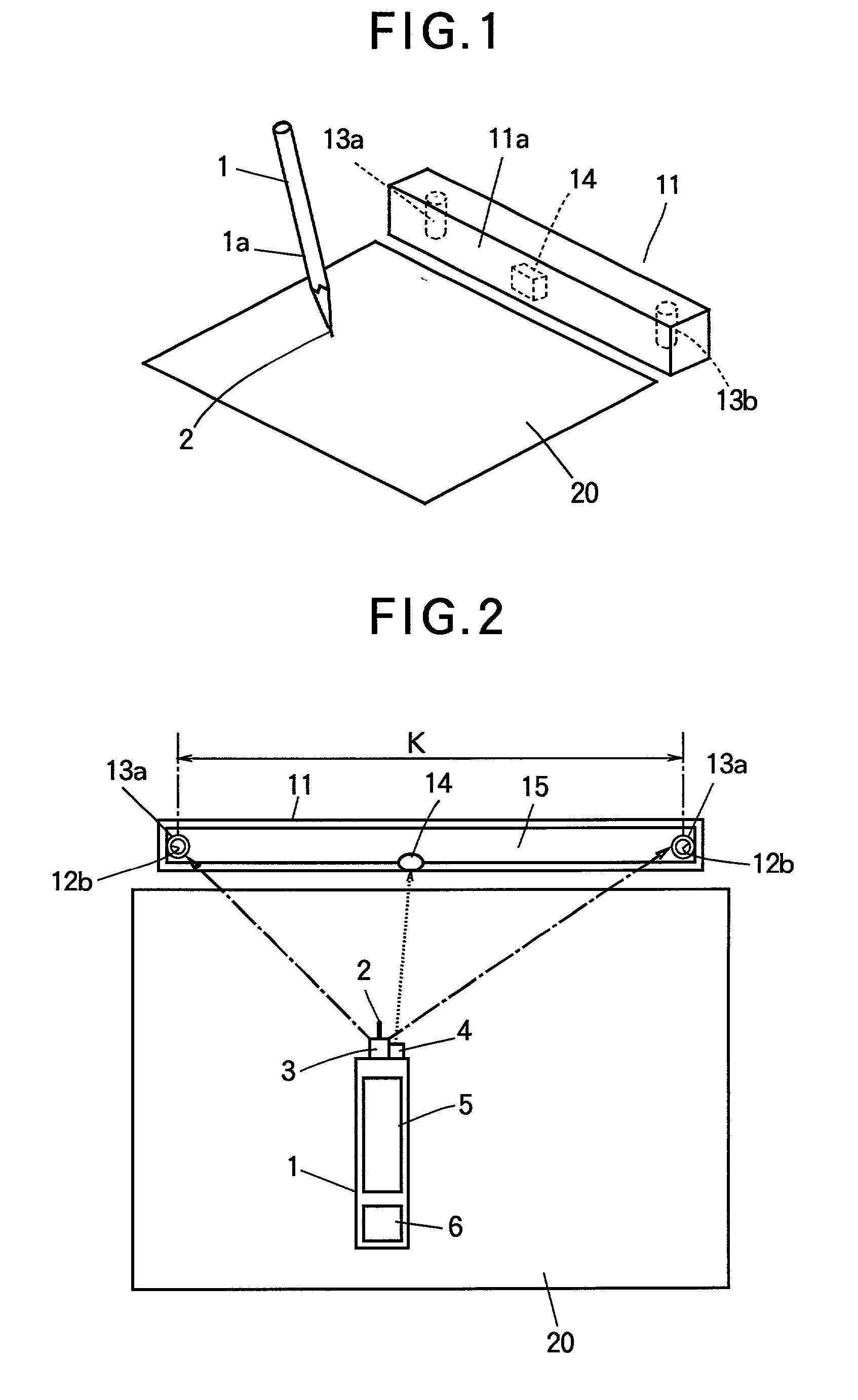
[0096] The fourth embodiment will now be described with reference to FIG. 9 and FIG. 10. When the writing member 2 of the pen 1 comes into contact with the input plane 20 at the point Q.sub.0 as shown in FIG. 9, the not-illustrated switch of the input pen is turned on to cause the ultrasonic oscillator 3 to emit the ultrasonic signal U.sub.S, and cause the LED 4 to emit the light signal ES at the same time through the drive circuit 105 shown in FIG. 8 (PEN-DOWN 1 in FIG. 10). As shown in FIG. 10(C), the ultrasonic signal U.sub.S is oscillating at the frequency f.sub.S while the writing member 2 is in contact with the input plane, that is, during the pen stroke. This ultrasonic signal U.sub.S is received by the ultrasonic receivers 13a, 13b, and converted into ultrasonic-reception signals U.sub.R, U.sub.L (electric pulse signals) by the ultrasonic-receiving circuits 25a, 25b. The light signal E.sub.S, which is a wave group including q pulses having the frequency p times (p being a po...


PUM


Abstract

A coordinate-capturing apparatus suitable for inputting handwritten characters or diagrams to a computer or a printer is disclosed. The apparatus includes an ultrasonic transmitter mounted on an input pen for transmitting ultrasonic waves, two ultrasonic receivers for receiving ultrasonic waves transmitted form the ultrasonic transmitter, and a distance calculating device for calculating distances between the input pen and the two ultrasonic receivers in order to determine coordinates representing a position of the input pen on the basis of the calculated distances. The apparatus of the invention can perform coordinate detection smoothly even when the input pen moves fast, and has reduced electric power consumption in the input pen to increase the life-span of a battery included in the input pen.

Description

[0001] The present invention relates to a coordinate-capturing apparatus, to be more specific, relates to a coordinate-capturing apparatus suitable for inputting handwritten characters or diagrams to a computer or a printer.[0002] There are various types of coordinate-capturing system using a tablet and an input pen, including a pressure-sensitive type, an electrostatic-coupling type, an electromagnetic-coupling type, an ultrasonic in-medium propagation (surface acoustic wave) type, and an ultrasonic aerial-propagation type.[0003] In each of the above conventional types except the ultrasonic aerial-propagation type, a sensor is built into a medium in the shape of a plate. Accordingly, they become too cumbersome to carry since their dimensions are determined by their input surfaces.[0004] On the other hand, the ultrasonic aerial-propagation type has not the constraint of the input surface, and any surface can be used as the input surface. Japanese Unexamined Utility Model Publication...

Claims


Application Information

Patent Timeline
Patent Type & Authority Applications(United States)
IPC IPC(8): G06F3/043G01B17/00G01S5/20G06F3/033
CPCG06F3/03545G06F3/043
Inventor TSUJI, KENZO
Owner OKI DATA CORP
Why Eureka
Try Eureka