Polarity reversal for fiber optic connections
- Summary
- Abstract
- Description
- Claims
- Application Information
AI Technical Summary
Benefits of technology
Problems solved by technology
Method used
Image
Examples
Embodiment Construction
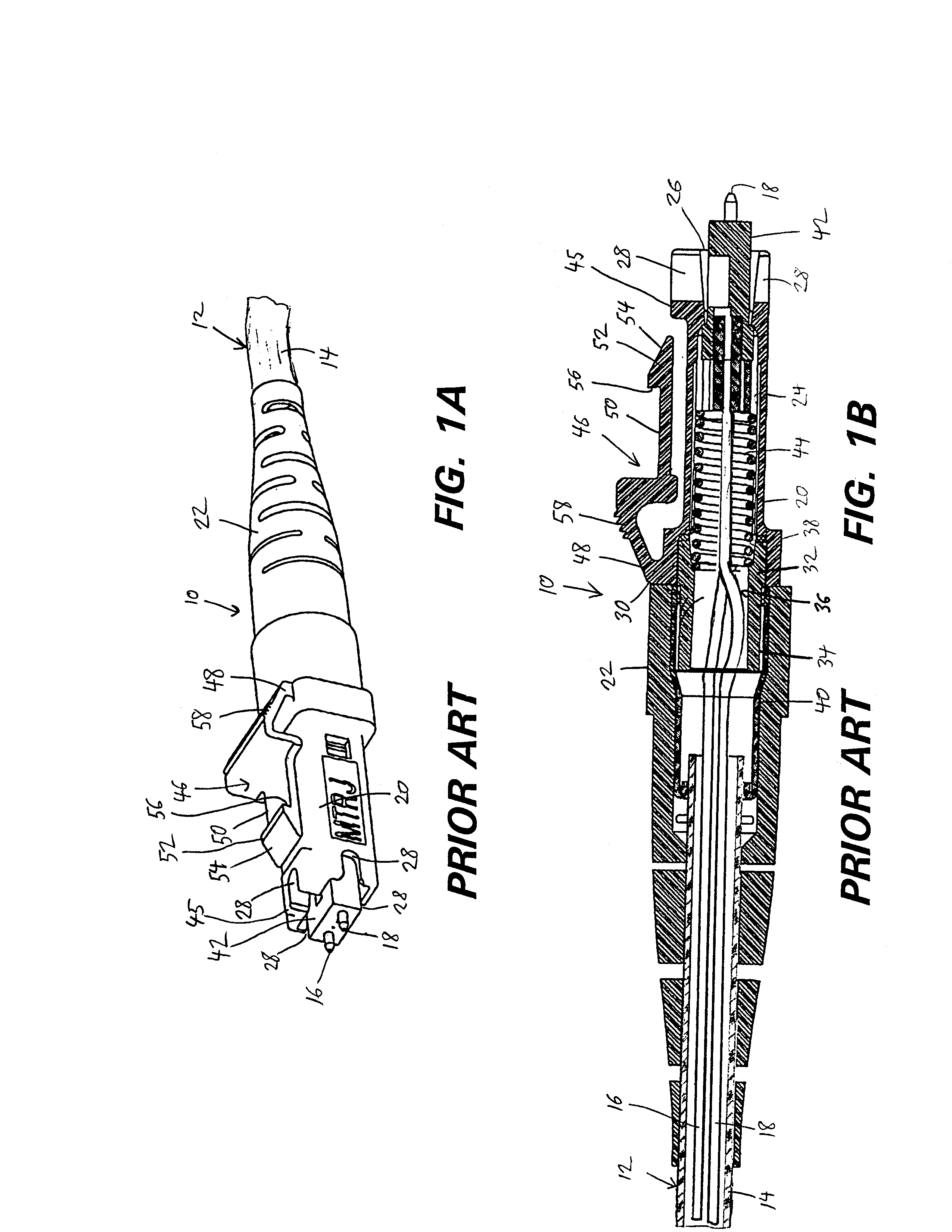
[0027] Referring first to Figures 1A and 1B, there is shown an exemplary prior art fiber optic cable end connector 10 shown affixed to one end of a fiber optic cable 12. The cable 12 includes an outer rubberized cover 14 that contains transmitting and receiving optic fibers 16, 18. The transmitting optic fiber 16 is used to transmit a signal along its length from a source (not shown) toward the end connector 10. The receiving optic fiber 18 receives a signal from the direction of the end connector 10 and transmits a signal along its length back to the source.
[0028] The end connector 10 includes a plastic housing 20 and a rubber cable sheath 22. As can be seen in Figure 1B, the transmitting and receiving fibers 16, 18 extend beyond the end of the cable cover 14 and extend independently into the housing 20.
[0029] The plastic housing 20 is roughly block-shaped and defines a chamber 24 therewithin that receives the individual fibers 16, 18. The forward end 26 of the plastic housing 20 p...
PUM
 Abstract
Description
Claims
Application Information
 - R&D
- Intellectual Property
- Life Sciences
- Materials
- Tech Scout
- Unparalleled Data Quality
- Higher Quality Content
- 60% Fewer Hallucinations
Browse by: Latest US Patents, China's latest patents, Technical Efficacy Thesaurus, Application Domain, Technology Topic, Popular Technical Reports.
© 2025 PatSnap. All rights reserved.Legal|Privacy policy|Modern Slavery Act Transparency Statement|Sitemap|About US| Contact US: help@patsnap.com


