Thermal Material-Processing Method

a material processing and material technology, applied in the field of material processing methods, can solve problems such as inaccurate clamping of workpieces

Active Publication Date: 2011-04-28
PROBEAM AG & CO KGAA
View PDF5 Cites 4 Cited by
  • Summary
  • Abstract
  • Description
  • Claims
  • Application Information

AI Technical Summary

Benefits of technology

[0010]An object of the present invention is to configure an electron-beam material-processing method of the type stated in the introduction in such a way that the deviation of the effective processing contour from the ideal processing contour is presented in readily comprehensible manner and in this way there is also the possibility of simple correction of this deviation.

Problems solved by technology

The geometrical deviations, in turn, may be both the cause of an inaccurate clamping of the workpiece and also the consequence of tolerance deviations to which the workpiece is subject in the course of manufacture.
A second cause of deviations between the working spot of the electron beam and the actual processing contour may consist in the fact that a residual magnetisation is present in the workpiece, under the influence of which the electron beam is deflected.
A further cause of the working spot not striking the actual processing contour, or not striking it everywhere, may consist in errors in the programming of the motion.

Method used


Image

  • Thermal Material-Processing Method
  • Thermal Material-Processing Method
  • Thermal Material-Processing Method

Examples


Embodiment Construction

[0038]While this invention is susceptible of embodiment in many different forms, there is shown in the drawings and will herein be described in detail one or more embodiments with the understanding that the present disclosure is to be considered as an exemplification of the principles of the invention and is not intended to limit the invention to the embodiments illustrated.

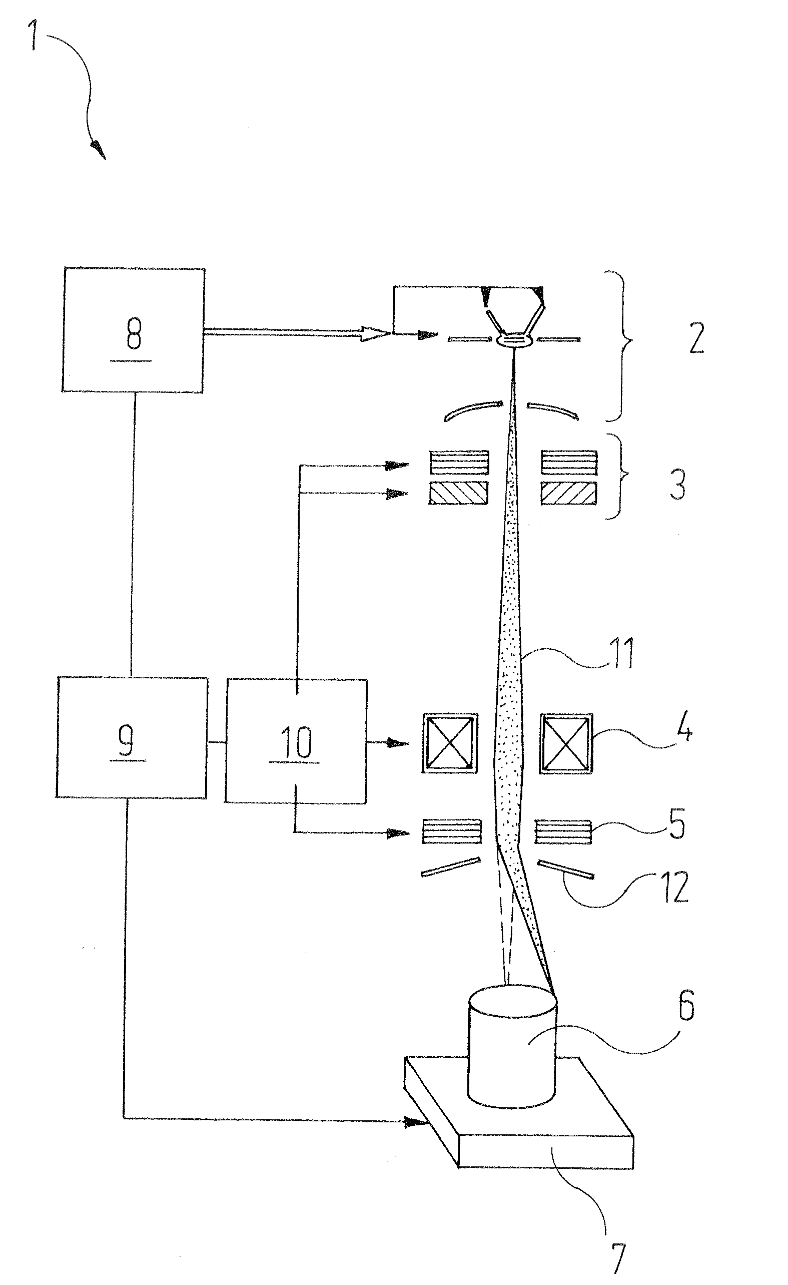
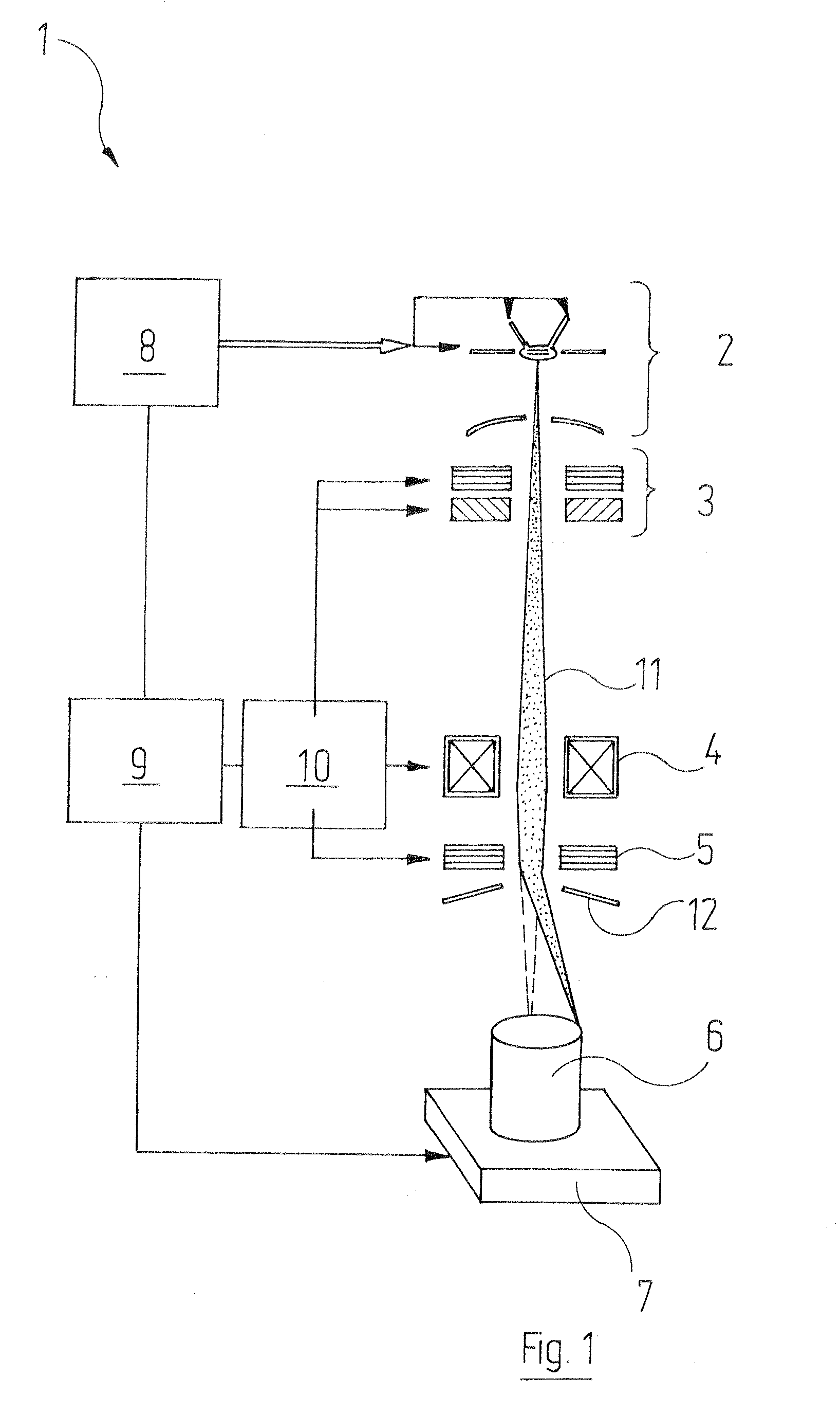
[0039]Reference will firstly be made to FIG. 1. This shows a unit for electron-beam welding, labelled overall by reference symbol 1, as is known as such. It will therefore be sufficient to describe it briefly.

[0040]The unit 1 comprises, in a vacuum-tight housing which is not represented, from top to bottom an electron-beam source 2, a centering and stigmator unit 3 including various deflecting electrodes, a focusing lens 4 comprising suitable coils, and also x-y deflection coils 5. The workpiece 6 stands on a manipulator 7 with which it can be moved in the x-y plane by means of a motor and with high precision.

[00...


PUM

PropertyMeasurementUnit
residual magnetisationaaaaaaaaaa
magnetic deflectionaaaaaaaaaa
energy densityaaaaaaaaaa

Abstract

A thermal material-processing method wherein between the working spot of an electron beam and a workpiece a relative motion is brought about. Prior to the actual thermal treatment an effective processing contour is ascertained, in that the working spot of the electron beam executes, in accordance with the stored data of an ideal processing contour, a relative motion in relation to the workpiece, and on this relative motion a scan motion is superimposed which is directed transversely to the ideal processing contour. In this manner, both geometrical and magnetically conditioned deviations of the points of incidence of the electron beam on the workpiece can be compensated.

Description

RELATED APPLICATIONS[0001]This application claims the filing benefit of German Patent Application No. 10 2009 050 521.0 filed Oct. 23, 2009 the contents of which are incorporated herein by reference.TECHNICAL FIELD[0002]The invention relates to a material-processing method wherein[0003]a) an electron beam is focused onto the surface of a workpiece:[0004]b) between the working spot of the electron beam and the workpiece a relative motion is brought about, in the course of which the working spot follows a processing contour;[0005]c) the relative motion between working spot and workpiece is controlled in accordance with control variables that a control device derives from a stored ideal processing contour.BACKGROUND OF THE INVENTION[0006]The quality of a thermal processing brought about with the aid of an electron beam—for example, a weld—depends to a great extent on how accurately the working spot of the electron beam strikes the desired processing contour—in the case of the welding o...

Claims


Application Information

Patent Timeline
Patent Type & Authority Applications(United States)
IPC IPC(8): B23K15/00
CPCB23K15/0013B23K15/0053H01J2237/3104H01J37/3005H01J37/3045B23K15/02
Inventor LOEWER, THORSTENFATH, JUERGEN
Owner PROBEAM AG & CO KGAA
Why Eureka
Try Eureka