
Non-redundant multi-error correcting binary differential demodulator

a demodulator and multi-error technology, applied in the field of binary differential demodulators, can solve the problems of increasing the complexity of the demodulator, and the performance of the bit error rate ber of the corresponding coherent demodulator, so as to reduce the memory requirements of the circuit, simplify the error detection and correction

Active Publication Date: 2008-04-17
NORTHROP GRUMMAN SYST CORP
View PDF10 Cites 4 Cited by
  • Summary
  • Abstract
  • Description
  • Claims
  • Application Information

AI Technical Summary

Benefits of technology

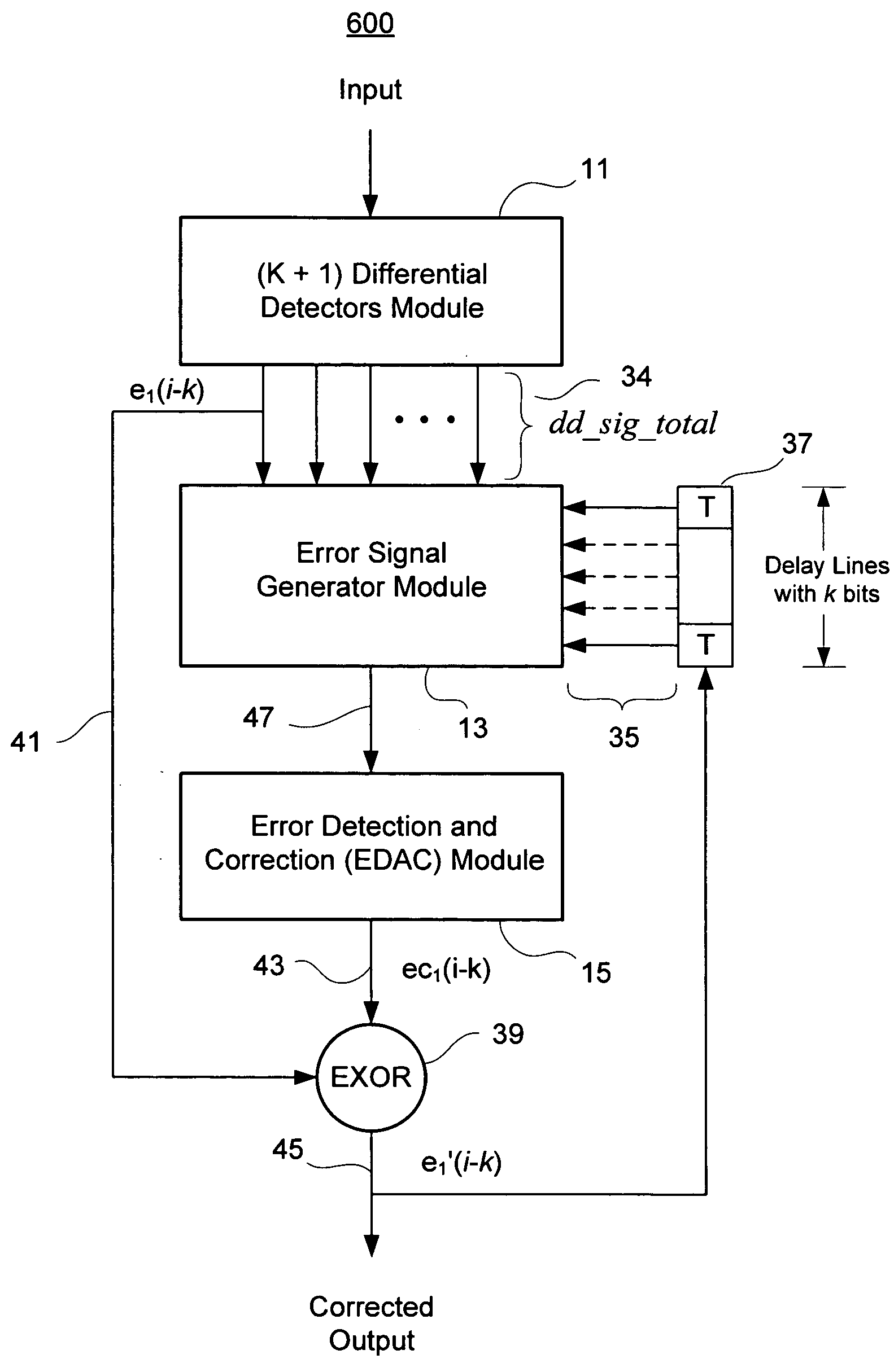
[0023]The present invention includes an algorithm for a non-redundant multi-error correcting binary differential demodulator that simplifies error detection and correction; and reduces memory requirements in circuits, software or methods embodying the algorithm. The demodulator includes a differential detectors (DD) module, an error signal generator (ESG) module, and an error detection-and-correction (EDAC) module. The DD module may contain a plurality of differential detectors. In one embodiment, the DD module receives a modulated input signal at each of (k+1) differential detectors, where k is an integer greater than zero. Each differential detector in the DD module produces an output, which may generate k counterparts by successive delay of k bits, thereby generating a total of (k+1)2 DD module outputs. The ESG module derives syndromes from the differential detector outputs and from feedback of corrected signals, such that the syndromes are orthogonal to an erroneous bit to be corrected. In one embodiment, the ESG module derives the syndromes by combining the (k+1)2 output signals with k corrected feedback signals. In another embodiment, the ESG module derives the syndromes using one or more outputs of a higher-order differential detector as a parity check for outputs of one or more lower-order differential detectors.

Problems solved by technology

However, their bit error rate BER performance is inferior to that for the corresponding coherent demodulators.
Coherent demodulators usually require carrier recovery and hence more complex circuits.
As the order of error-correcting capability increases, the order of deployed differential detectors, and hence the demodulator complexity increase.
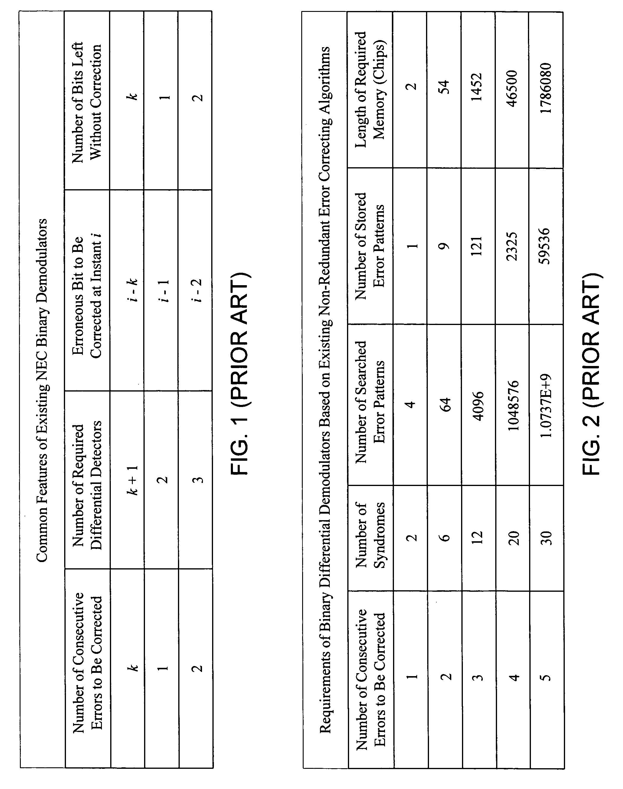
The algorithms used in existing NEC binary demodulators impose requirements that limit the performance of those demodulators.
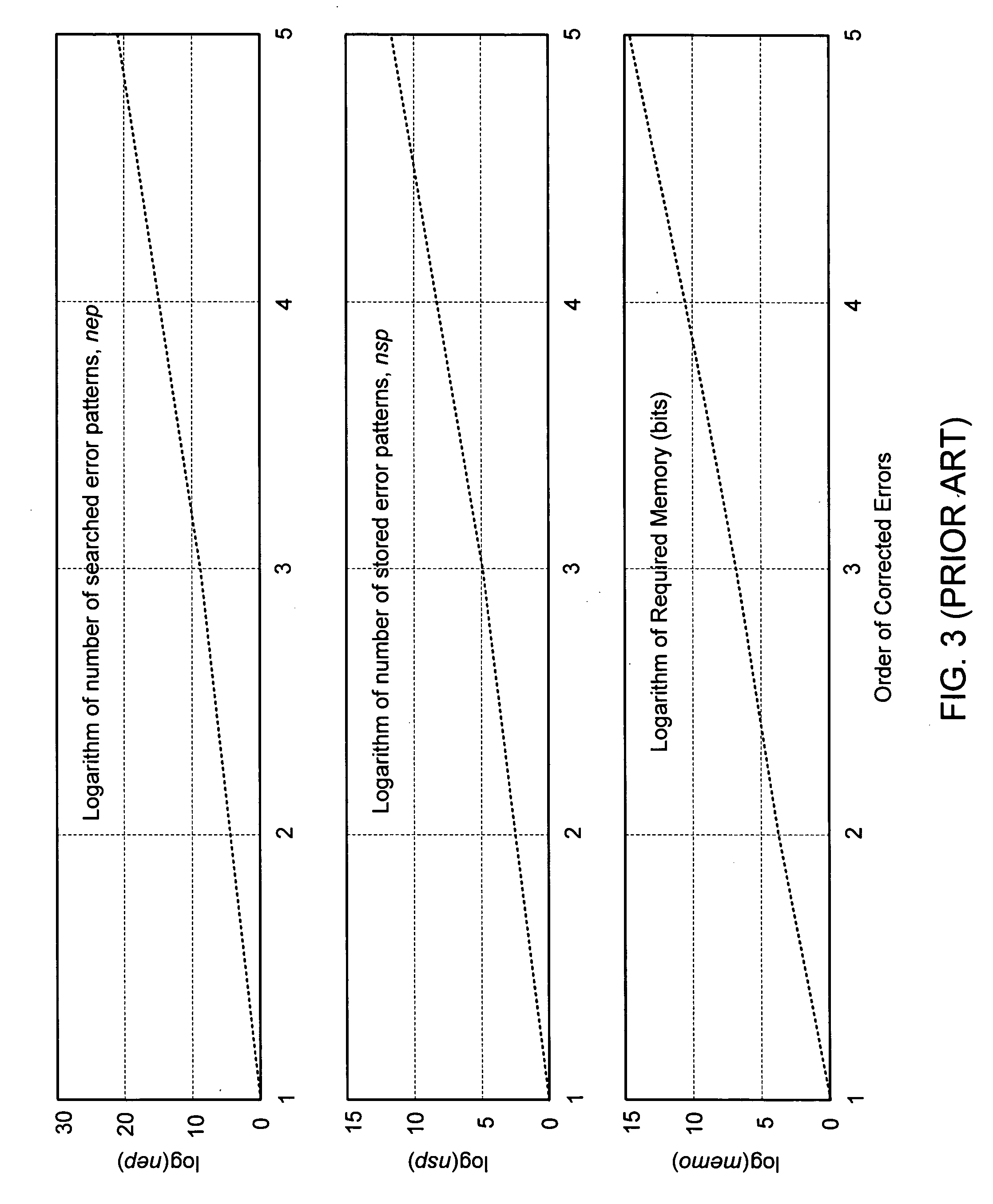
Such requirements discouraged the design of future demodulators with higher order error correcting capabilities, e.g. triple-error correcting capability, quadruple-error correcting capability, etc.
This makes pattern detection processes deployed within existing demodulators more time consuming, more memory demanding, and less accurate.
These drawbacks have discouraged further design of NEC binary demodulators having higher order error correcting capabilities.
b) The use of delayed syndrome values by the syndrome registers makes the demodulators more vulnerable to error propagation.
As for pattern detectors, they impose the following limitations:
a) Pattern detectors require memories to store specified error patterns. Both the number of stored error patterns, and the length of required memory increase exponentially as the order of error correcting capabilities increases; and
b) Pattern detector processes performed within any pattern detector consume time and they may be associated with uncertainties, especially at higher-order correcting capabilities.

Method used


Image

  • Non-redundant multi-error correcting binary differential demodulator
  • Non-redundant multi-error correcting binary differential demodulator
  • Non-redundant multi-error correcting binary differential demodulator

Examples


Embodiment Construction

[0046]The present invention provides a robust algorithm for the design of non-redundant multi-error correcting binary differential demodulators. The objective of the present invention is twofold: (i) enhancing existing double-error correcting binary demodulators, and (ii) designing demodulators with higher order-error correcting capabilities. In achieving these objectives, the present invention provides a robust algorithm for designing multi-error correcting binary differential demodulators that have the following novel features:

[0047](a) An ESG module that replaces both syndrome generators and syndrome registers used in existing demodulators. Advantageously, the ESG module does not use delayed syndrome values, which reduces demodulator vulnerability to error propagation.

[0048](b) An EDAC module that replaces pattern detectors of existing demodulators. The EDAC module uses threshold values in detecting and correcting errors. This eliminates pattern detection processes, and the memor...


PUM


Abstract

An algorithm for a non-redundant multi-error correcting binary differential demodulator simplifies error detection and reduces memory requirements in circuits embodying the same. The demodulator includes a differential detectors (DD) module, an error signal generator (ESG) module, and an error detection-and-correction (EDAC) module. The DD module receives modulated binary input at each of (k+1) differential detectors, each producing (k+1) outputs. The ESG module combines the (k+1)2 output signals with k corrected feedback signals to derive syndromes orthogonal to an erroneous bit to be corrected and generates 2k error signals from the syndromes. The EDAC module generates a correction factor from the 2k error signals and combines the factor with the output of the first order detector delayed by k bits to correct an erroneous bit. The k corrected feedback signals may be derived by successively delaying the corrected erroneous bit. Simplified higher order demodulators may be constructed using a nested hierarchy of lower order demodulators based on the algorithm.

Description

BACKGROUND OF THE INVENTION[0001]1. Field of the Invention[0002]The present invention relates to binary differential demodulators. More specifically, the invention relates to non-redundant multi-error correcting differential demodulators for binary digital frequency or digital phase modulated signals.[0003]2. Description of Related Art[0004]Differential demodulators have been widely used in varieties of communication systems that use either digital frequency or digital phase modulated signals. Among those systems are IFF communication systems, underwater communication systems, mobile communication systems, satellite communication systems, etc. Differential demodulators require simpler circuits and they do not require carrier recovery. However, their bit error rate BER performance is inferior to that for the corresponding coherent demodulators. Coherent demodulators usually require carrier recovery and hence more complex circuits.[0005]Non-redundant error correcting (NEC) techniques ...

Claims


Application Information

Patent Timeline
Patent Type & Authority Applications(United States)
IPC IPC(8): H03M13/00
CPCH03M13/03
Inventor KARAM, MOSTAFA A.
Owner NORTHROP GRUMMAN SYST CORP
Learn More