Optical fiber

a technology of optical fiber and cladding, applied in the field of optical fiber, can solve the problems of ambiguity in the specification of the structure based on the effective refractive index, the inability to reliably realize desired characteristics, and the assumption that the structure having a non-uniform refractive index distribution can be replaced by a homogeneous medium

Inactive Publication Date: 2001-10-11
SUMITOMO ELECTRIC IND LTD
View PDF0 Cites 44 Cited by
  • Summary
  • Abstract
  • Description
  • Claims
  • Application Information

AI Technical Summary

Problems solved by technology

However, as the optical wavelength becomes shorter, the light is locally concentrated at portions having the high refractive index and hence, it is considered that the assumption that the structure having a non-uniform refractive index distribution can be replaced by a homogeneous medium will lose the validity.
As a result, it should be noted that specification of the structure based on effective refractive index is inevitably ambiguous.
In the conventional microstructured optical fiber in which the void diameters in cross section are not uniform, it is difficult to securely realize desired characteristics.
For example, when the void diameters are small, the surface tension strongly acts and hence, the contraction is liable to occur compared with the case in which the void diameters are large.
As a result, it is difficult to perform the fiber drawing such that each of the voids having different diameters is formed in the fiber with the desired diameters.
The wavelength band in the vicinity of the locally-zero-dispersion wavelength cannot be used for the wavelength division multiplexing transmission due to the deterioration of the transmission quality dei to the nonlinear optical phenomena generated among optical signals having different wavelengths.

Method used


Image

  • Optical fiber
  • Optical fiber
  • Optical fiber

Examples


second embodiment

[0066] Subsequently, the optical fiber according to the present invention is explained. FIG. 6 is a cross-sectional view in a fiber axial direction (longitudinal cross-sectional view) of an optical fiber 10a according to the present invention. Further, FIG. 7 and FIG. 8 are respectively transverse cross-sectional views of this optical fiber 10a taken along a line VII-VII and a line VIII-VIII of FIG. 6.

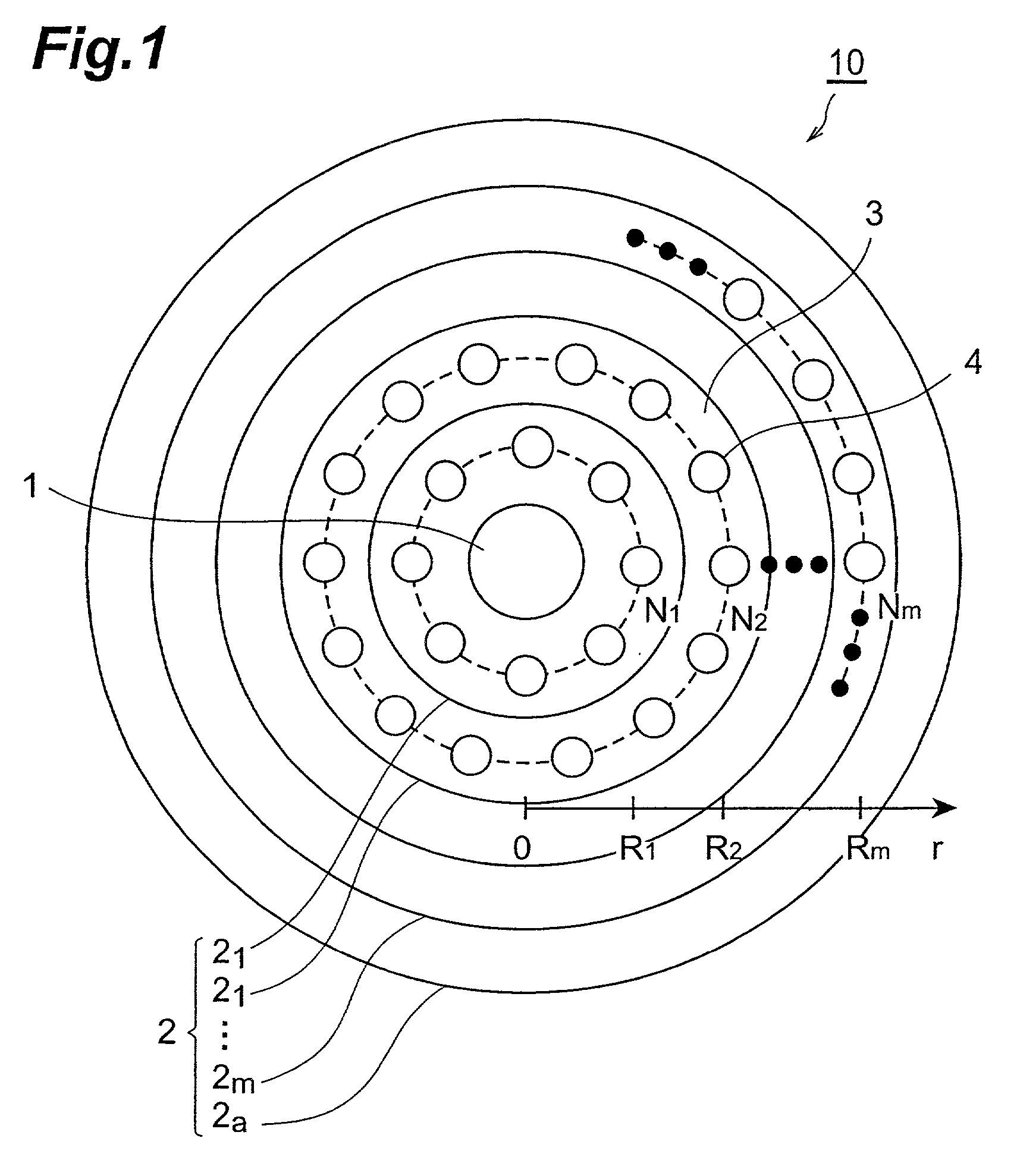
[0067] This optical fiber 10a includes a core region 1 and a cladding region 2 which surrounds the core region 1. The core region 1 is made of silica glass doped with Ge. With respect to the cladding region 2, in the pure silica glass which constitutes the main medium, a plurality of, that is, N pieces (8 pieces in FIG. 7) of voids 4 which open in an axial direction at a section A and transition sections C sandwiching the section A disposed in an axial direction which will be explained later are arranged on a circumference having its center at the center of the core region 1 in the cro...

first embodiment

[0083] Here, although the case in which the circular annular region including the voids 4 is made of a single layer has been explained, it may be possible to adjust the refractive index distribution in cross section by adopting the multi-layered circular annular region and adjusting the structural density as has been explained with respect to the

[0084] Subsequently, the third and the fourth embodiments of the optical fiber according to the present invention are explained in conjunction with FIG. 12A, FIG. 12B and FIG. 13. FIG. 12 A is a transverse cross-sectional view showing the third embodiment of the optical fiber according to the present invention, FIG. 12B is a transverse cross-sectional view showing the fourth embodiment of the optical fiber according to the present invention, and FIG. 13 is a transverse cross-sectional view showing a conventional microstructured optical fiber.

[0085] In the conventional microstructured optical fiber 10f shown in FIG. 13, a large number of void...


PUM

PropertyMeasurementUnit
mean refractive index distributionaaaaaaaaaa
refractive indexaaaaaaaaaa
refractive index distributionaaaaaaaaaa

Abstract

In an optical fiber composed of a core region and a cladding region surrounding the core region and having a plurality of regions made of sub mediums having refractive indices different from a refractive index of a main medium disposed in a main medium constituting this cladding region, these regions made of the sub mediums are arranged in one given or a plurality of a given circular annular regions and the centers of the regions made of the sub mediums in respective circular annular regions are arranged on the same circumference centered at the center of the core.

Description

[0001] This application claims priority to Provisional Application Serial No. 60 / 246,761 filed Nov. 9, 2000, and No. 60 / 246,725 filed Nov. 9, 2000 which are hereby incorporated by reference in its / their entirety.[0002] 1. Field of the Invention[0003] The present invention relates to an optical fiber which can be suitably used as an optical transmission path and a dispersion compensator.[0004] 2. Description of the Related Art[0005] FIG. 14 is a cross-sectional view showing a central portion of an optical fiber including microstructures which has been known conventionally. This optical fiber has a structure in which silica glass 61 constitutes a main medium and a large number of voids (vacant holes) 62 are disposed in a cross section thereof. A central portion in cross section having no voids 62 constitutes a core region 63 and a portion surrounding the core region 63 and including a large number of voids 62 constitutes a cladding region 64.[0006] The principle of light confinement o...

Claims


Application Information

Patent Timeline
Patent Type & Authority Applications(United States)
IPC IPC(8): C03B37/012C03B37/025C03B37/027C03C25/62G02B6/02
CPCC03B37/01231C03B37/0253C03B37/027C03B37/02727C03B37/02763C03B37/02781C03B2203/14C03B2203/18C03B2203/36C03B2203/42C03B2205/08C03B2205/10C03B2205/20C03C25/6206G02B6/02033G02B6/02228G02B6/02247G02B6/02276G02B6/02333G02B6/02347G02B6/02357G02B6/02361G02B6/02376G02B6/03627
Inventor HASEGAWA, TAKEMISASAOKA, EISUKENISHIMURA, MASAYUKIONISHI, MASASHI
Owner SUMITOMO ELECTRIC IND LTD
Why Eureka
Try Eureka