Multiple label fluorescence polarization assay system and method

a fluorescence polarization assay and label technology, applied in the field of biochemical assays, can solve the problems of no system or method for measuring an fp assay with multiple probes, complicated measurement of fp, etc., and achieve the effect of accurately calculating fp or fa

Inactive Publication Date: 2001-10-25
CAMBRIDGE RES & INSTR
View PDF0 Cites 79 Cited by
  • Summary
  • Abstract
  • Description
  • Claims
  • Application Information

AI Technical Summary

Benefits of technology

0026] The core of the invention is the quantification of FP for multiple probes through measurement of the cross-talk by means of the instrumental response matrix A, or an equivalent formalism, and the use of this cross-talk information to...

Problems solved by technology

Measurements of FP are complicated by the presence of contaminant signals such as background ...

Method used


Image

  • Multiple label fluorescence polarization assay system and method
  • Multiple label fluorescence polarization assay system and method
  • Multiple label fluorescence polarization assay system and method

Examples


Embodiment Construction

[0040] Throughout this discussion, the instrument and method are described for two labels, but the principle can be extended to three or more labels using the same methodology. Also, where analysis and algorithms are presented in the form of particular algebraic equations or matrices, this is purely for the purpose of explaining the invention; one may use other equations or algorithms that achieve the same end in order to practice the invention.

[0041] Throughout the following, one state of polarization is termed h and its complement is v. These need not be horizontal and vertical, but either h or v must correspond to the major axis of the state of polarization used to excite the sample in any given measurement.

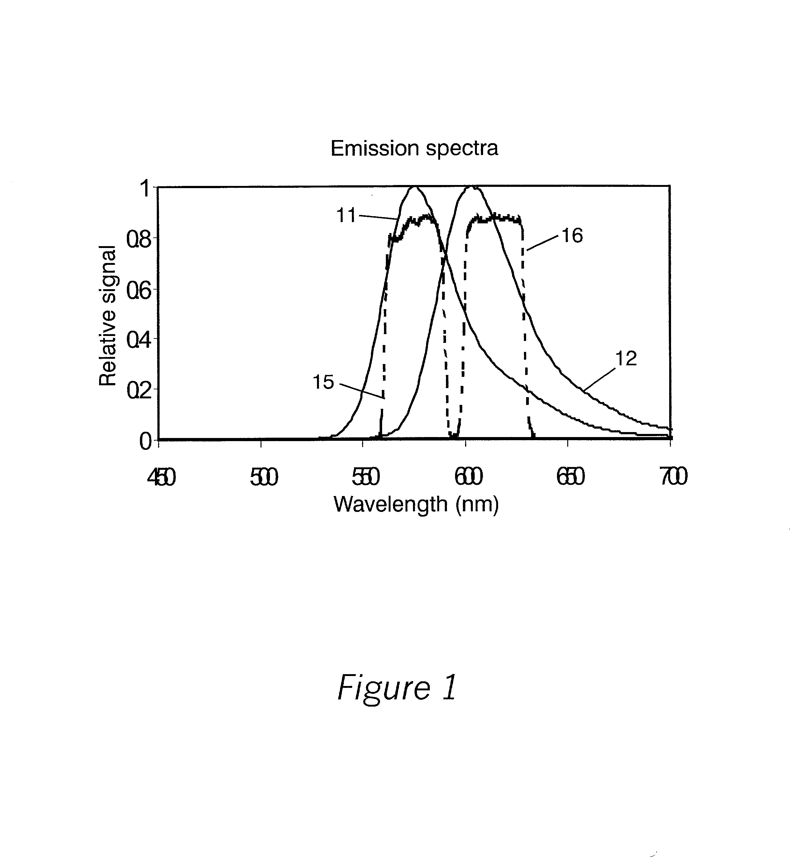
[0042] FIG. 1 shows the emission spectra 11 and 12 of two probes whose fluorescent emissions are measured after passing through bandpass filters having respective transmission bands 15 and 16. These are chosen so that band 15 includes spectra 11, and band 16 includes spectra 1...


PUM


Abstract

A sample having a plurality of probe molecules is illuminated with at least one beam of excitation light that is linearly polarized along a first axis, thereby effecting fluorescence emission in a plurality of spectral bands. The intensity of a first component of fluorescence emission that is polarized along the first axis, as well as the intensity of a second component of fluorescence emission that is polarized along an orthogonal second axis, is measured for each of said plurality of spectral bands. These measurements are represented as a measurement vector M. Since each probe emits some limited amount of light in the characteristic band of another probe, this results in cross-talk between probes. The measurement vector is therefore corrected using an instrument response matrix A, which is generated by measuring the flux output of control samples which each have only a single probe species. A flux vector S is calculated according to S=A.sup.-1M, and the fluorescence polarization FP is calculated from the S values.

Description

RELATED APPLICATIONS[0001] This application claims priority from U.S. Provisional Patent Application Ser. No. 60 / 184,844 which was filed on Feb. 25, 2000.BACKGROUND OF THE INVENTION[0002] 1. Field of the Invention[0003] The invention is directed toward biochemical assays, more particularly toward assays using fluorescence polarization detection with two or more fluorescent labels in the experiment.[0004] 2. Description of the Related Art[0005] Fluorescence polarization (FP) assays are becoming popular, since they are homogeneous and relatively safe, with no radioactive material. A good discussion is provided in the recent review article by John Owicki entitled "Fluorescence Polarization and Anisotropy in High Throughput Screening: Perspectives and Primer", published in the Journal of Biomolecular Screening, Volume 5, No. 5, pp 297-306 (2000).[0006] The technique has at its core the detection of relative intensity of fluorescence emission in two orthogonal states of polarization. The...

Claims


Application Information

Patent Timeline
IPC IPC(8): G01N21/64
CPCG01N21/6428G01N21/6445G01N21/6452G01N2021/6421G01N2021/6441G01N2021/6471
Inventor HOYT, CLIFFORD C.
Owner CAMBRIDGE RES & INSTR
Why Eureka
Try Eureka