
Clutch actuation system with auxiliary actuating assembly

Inactive Publication Date: 2001-11-08
ZF FRIEDRICHSHAFEN AG
View PDF0 Cites 49 Cited by
  • Summary
  • Abstract
  • Description
  • Claims
  • Application Information

AI Technical Summary

Benefits of technology

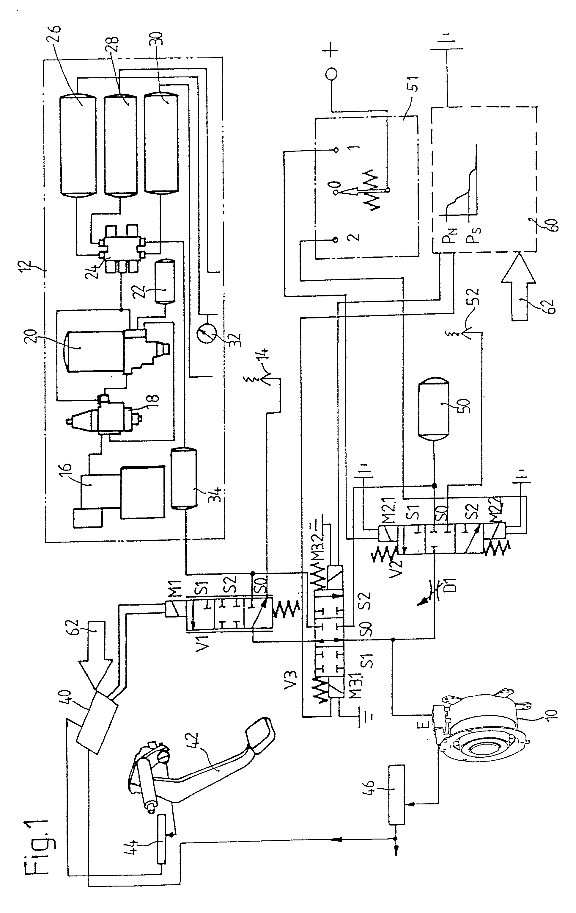
[0011] According to the invention, the auxiliary actuation by the pressure medium-powered cylinder assembly, preferably a pneumatically powered cylinder assembly, is accomplished by means of an auxiliary actuating valve assembly, which can be switched into a pressure medium feed position, in which the pressure medium-powered cylinder assembly is in pressure medium flow connection with the pressure medium source or with a separate auxiliary pressure medium source for the emergency actuation of the clutch. Alternatively or additionally, the auxiliary actuating valve assembly can be switched to a pressure medium discharge position, in which the pressure medium-powered cylinder assembly is in pressure medium flow connection with a pressure compensation port or a pressure compensation tank for the emergency actuation of the clutch. A central auxiliary actuation function is present as soon as it becomes possible for the clutch to be disengaged by the intermediate action of the auxiliary actuating valve assembly, so that, even though a gear is engaged and the drive train is under tension, the gear can still be disengaged and the drive unit (the engine) can be started for the purpose of, for example, refilling the pneumatic or compressed air tank of the pressure medium source, which in this case is designed as a pneumatic source. Preferably, however, the clutch can be both disengaged and engaged by the intermediate action of the auxiliary actuating valve assembly. Thus it becomes possible not only for an engaged gear to be disengaged and for the drive unit to be started, but also for a gear to be made available for an emergency drive function, so that the vehicle can be driven out of a danger area or even driven to a repair garage (limp-home function). It would be ideal for the intermediate action of the auxiliary actuating valve assembly to make possible several engagements and disengagements or disengagements and engagement of the friction clutch by the appropriate switching of the auxiliary actuating valve assembly back and forth several times between the pressure medium flow position and the pressure medium discharge position. Only in this way is a truly complete limp-home function realized, in which the vehicle can move under its own power over a relatively long distance.
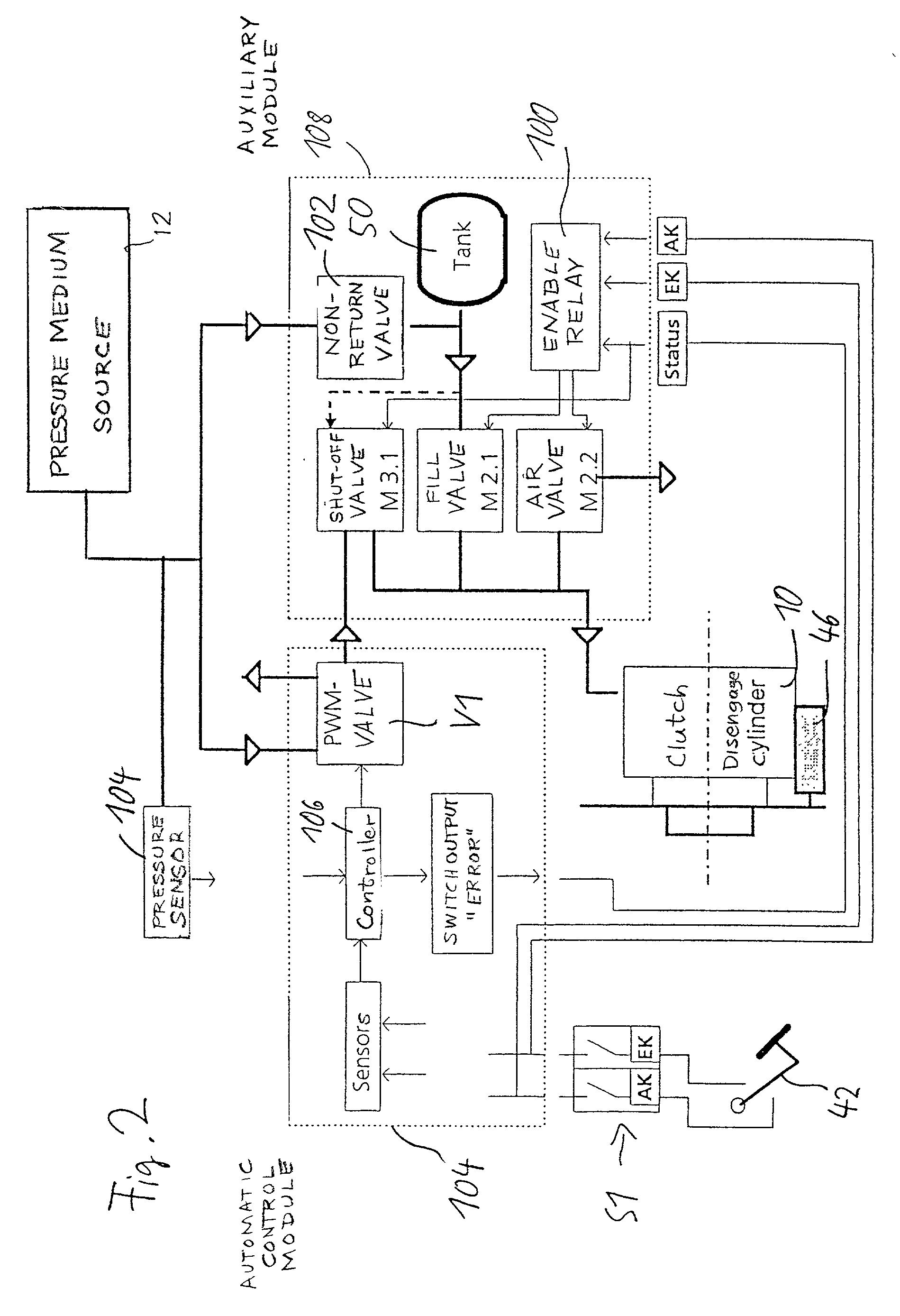
[0013] Although it is conceivable that the auxiliary actuating valve assembly could belong at least in part to the pilot / automatic control assembly, it is preferable with respect to redundancy and thus an increase in operational reliability that the auxiliary actuating valve assembly be a valve assembly separate from the pilot / automatic control valve assembly.
[0024] In accordance with a third aspect of the invention, the auxiliary actuating assembly includes an auxiliary pressure medium tank separate from the pressure source, which tank can be brought into pressure medium flow connection with the pressure medium source via an associated valve assembly in order to fill the auxiliary pressure medium tank with pressure medium. This auxiliary tank can be brought via the valve into pressure medium flow connection with the pressure medium-powered cylinder assembly in order to actuate the clutch, preferably to disconnect it. The auxiliary tank can be isolated by means of the valve assembly from the rest of the pressure medium system, including the pressure medium source and the pressure medium-powered cylinder assembly, in order to keep the pressure medium in the auxiliary pressure medium tank available for use in emergency actuation situations. The auxiliary pressure medium tank makes it possible for the clutch to be actuated in auxiliary mode independently of the pressure medium source.
[0025] The valve assembly preferably has at least one nonreturn valve, which, as a function of at least one pressure medium pressure being applied to it, enables and blocks the pressure medium flow connection between the pressure medium source and the auxiliary pressure medium tank. It is advantageous for the assembly to be designed so that a valve does not have to be actuated separately to fill the auxiliary pressure medium tank, but rather so that the nonreturn valve always opens automatically to allow the filling of the auxiliary pressure medium tank whenever the pressure medium source is supplying sufficient pressure.
[0027] It is advantageous to provide a throttle point in a pressure medium flow connection associated with the pressure medium-powered cylinder assembly, so that an auxiliary clutch-engaging time and / or an auxiliary clutch-disengaging time can be set.

Problems solved by technology

For example, after the vehicle in question has been parked for a certain period of time, the compressed air tank of the pressure medium source can become completely empty as a result of leaks in the individual receivers.
If the vehicle was parked with a gear engaged, the tension of the drive train would make it impossible to disengage the gear without emergency or auxiliary actuation of the clutch, and the vehicle's engine could therefore not be started to fill the compressed air tank back up again.
It is generally known, for example, that various components, such as electronic components, can fail and that in such a situation the vehicle must be taken to the nearest garage still under its own power if possible and possibly in a manner deprived of a certain convenience.
For example, the auxiliary actuation of a clutch of this type requires the driver to exert a great deal of force on the clutch pedal, which the driver can do only with great effort.
In addition, the auxiliary actuation system represents a high degree of mechanical and hydraulic complexity.
Because the components must be very strong, they must also be correspondingly heavy and bulky.
The auxiliary actuation system therefore also occupies a considerable amount of space.
In addition, it is disadvantageous on principle to provide a hydraulic slave cylinder assembly inside a clutch cover, because these cylinders can leak, and the escape of the hydraulic oil can cause damage.
A disengaging system of this type appears to be too complicated for modern, electronically controlled drive trains, nor is it very satisfactory with respect to positioning accuracy.
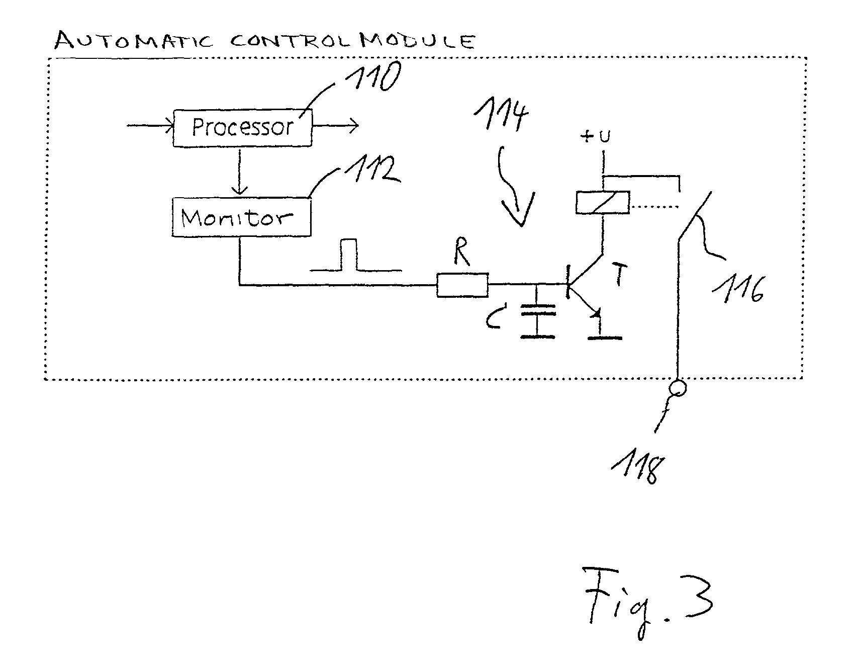
In addition, it will usually be advisable for an error criterion to pertain to the availability of the minimum pressure medium pressure required for normal actuation of the clutch.

Method used


Image

  • Clutch actuation system with auxiliary actuating assembly
  • Clutch actuation system with auxiliary actuating assembly
  • Clutch actuation system with auxiliary actuating assembly

Examples


Embodiment Construction

[0038] FIG. 1 shows the system components of a commercial vehicle, including a clutch actuation system in accordance with a preferred embodiment of the invention. The actuation system comprises a pressure medium-powered cylinder 10, designed as a ring-type pneumatic cylinder, installed in a housing bell between a transmission and an internal combustion engine. This cylinder serves to actuate a friction clutch, which connects the transmission to the engine. The pressure medium-powered cylinder 10 has a pneumatic connection E, which leads to a compressed air or pneumatic source 12 and to a pressure compensation port 14 by way of a mode valve V3, formed by a 3 / 4-way valve, and a pilot / automatic control valve V1, which is designed here as a 3 / 3-way proportional valve. The pneumatic source 12 includes various components known in and of themselves, including, for example, a belt-driven compressor 16; a pressure-regulating valve 18; an air drier 20; a compressed air tank 22 associated with...


PUM


Abstract

An actuation system for a friction clutch installed in the drive train of a motor vehicle between a drive unit and a transmission includes a pressure medium-powered cylinder assembly and a pilot / automatic control valve assembly. An auxiliary actuating assembly includes an auxiliary actuating valve assembly, which can be switched into a pressure medium feed position, wherein the pressure medium-powered cylinder assembly can be connected with the pressure medium source or with a separate auxiliary pressure medium source for emergency actuation of the clutch, and into a pressure medium discharge position, wherein the cylinder assembly can be connected with a pressure compensation port or with a pressure compensation tank.

Description

[0001] 1. Field of the Invention[0002] The invention pertains to an actuation system for a friction clutch installed in the drive train of a motor vehicle, especially a commercial motor vehicle, between a drive unit, especially an internal combustion engine, and a transmission. This actuation system includes a pressure medium-powered cylinder assembly which is used to actuate the friction clutch; a pilot / automatic control valve assembly connected to the source of the pressure medium, by means of which the pressure medium-powered cylinder assembly can be actuated as a function of a control input representing a desired actuation state, possibly the desired position of a disengaging device, and an actual value representing an actual actuation state, possibly the actual position of the disengaging device. An auxiliary actuating assembly is provided for clutch actuation independently of the ability of the valve assembly to function and / or independently of the ability of a pilot / automatic...

Claims


Application Information

Patent Timeline
IPC IPC(8): F16D48/02F16D48/06
CPCF16D25/14F16D48/02F16D48/066F16D2048/0254F16D2500/1028
Inventor NAGLER, FRANZFLIEGE, HANS
Owner ZF FRIEDRICHSHAFEN AG
Learn More