
Closed catheter suction system

a closed catheter and suction system technology, applied in the direction of suction devices, intravenous devices, couplings, etc., can solve the problems of increasing the risk of patient hypoxia, no device or method for an isolated rinsing procedure is disclosed, and increasing the risk of hypoxia

Inactive Publication Date: 2001-11-22
ELKINS JOHN I
View PDF0 Cites 69 Cited by
  • Summary
  • Abstract
  • Description
  • Claims
  • Application Information

AI Technical Summary

Benefits of technology

[0017] Another object of the present invention is to provide a closed catheter suction system that prevents aspirated secretions from re-entering the passageway of the patient during subsequent rinsing of the suction catheter lumen.
[0018] A further object of the present invention is to provide a closed catheter suction system which prevents a lavage solution from inadvertently entering the ventilation circuit and causing bacterial contamination.
[0019] Yet a further object of the present invention is to provide a closed catheter suction system that prevents the accidental loss of ventilator volume through the lavage port(s).

Problems solved by technology

Unfortunately, the rinsing procedure that follows patient aspiration increases the risk of hypoxia since the flow of oxygen to the patient remains interrupted.
Several prior art closed catheter suction systems equipped with rinse ports interrupt the supply of oxygen to the patient during the rinse procedure, and as a result, increase the risk of patient hypoxia because the rinse port is not isolated from the ventilation circuit.
U.S. Pat. No. 5,125,893 to Dryden does disclose a suction catheter which can be removed from the ventilation circuit adapter through a one-way valve, however, no device or method for an isolated rinsing procedure is disclosed.
If a rinsing procedure were attempted with the Dryden device, the lavage solution and the infectious secretions would likely exit the tip of the catheter and enter the sheath, resulting in possible contamination of the ventilation circuit since Dryden concedes that some leakage through the one-way valve will occur.
The special adapter is undesirable because connecting and disconnecting accessories to and from the ventilation circuit places the sterile environment at a substantial risk of contamination.
Moreover, if the fluid entry port were used as a lavage port to clear secretions, the lavage could flow into the ventilator circuit, thereby resulting in undesirable moisture accumulation and potential bacterial growth.
Accordingly, an additional disadvantage of a rinse port which is not isolated from the ventilation circuit is that the rinse solution instilled through the port may inadvertently flow into the ventilation tubing and ultimately compromise the health of the patient.
Rinse ports disclosed in the prior art are often disadvantageously positioned at the proximal end of the closed catheter suction system which requires the rinse solution to travel the entire length of the suction catheter to the distal end thereof and then travel back to the vacuum source located at the proximal end.
Such a procedure presents the risk of transporting any residual infectious secretions within the lumen of the suction catheter back into the patient when the rinse solution is instilled.
If the infectious secretions do in fact enter the patient, the secretions must be suctioned back out of the patient and the lumen must again be rinsed, resulting in a vicious cycle of contamination and an extremely inefficient procedure.
Since rinsing procedures generally occur immediately after the aspiration procedure when the patient is hypoxic, several cycles of suctioning and rinsing can compromise the health of the patient over an extended period of time.
Regrettably, the prior art is deficient because the location of the rinse port along the closed catheter suction system presents the risks of transporting residual infectious secretions back into the patient and inducing severe hypoxia in the patient from the necessitous cycle of aspiration and rinsing.
Unfortunately, a lavage port located at the distal end of a closed catheter suction system may introduce lavage into the ventilation tubing if the ventilator circuit and the closed catheter suction system are not positioned properly.
For example, when the closed catheter suction system is placed in certain positions, gravity often causes the saline lavage to inadvertently enter the ventilator tubing instead of the endotracheal or tracheostomy tube.
If the saline lavage enters the ventilation tubing, the resulting moisture along the tubing can promote undesirable bacterial growth and compromise the health of the patient.
When the cap is inadvertently left open or off, partial loss of ventilator volume to the patient can result and infectious pathogens from the patient could also be exuded from the open port.
Moreover, partial loss of ventilator volume can lead to hypoxia and result in an increased risk to the health of the patient.
If infectious pathogens are exuded from the open port, the health of surrounding medical staff and visitors are also placed at risk.
Unfortunately, the extra safety step to lock the valve is often overlooked by medical staff, therefore further compromising the health of the patient if the patient were to accidentally activate the valve under the mistaken belief that the locking valve was the nurse call bell.
If a patient or member of the medical staff were to pull on the catheter system, the outer envelope or sheath could tear, causing the catheter to be pulled from the ventilation circuit and thereby causing a leak in the circuit and inhibiting the requisite delivery of oxygen to the patient.
Excessive time in correcting the leak can result in severe hypoxia, hypercapnia, or cardiac arrest in a patient.

Method used


Image

  • Closed catheter suction system
  • Closed catheter suction system
  • Closed catheter suction system

Examples


Embodiment Construction

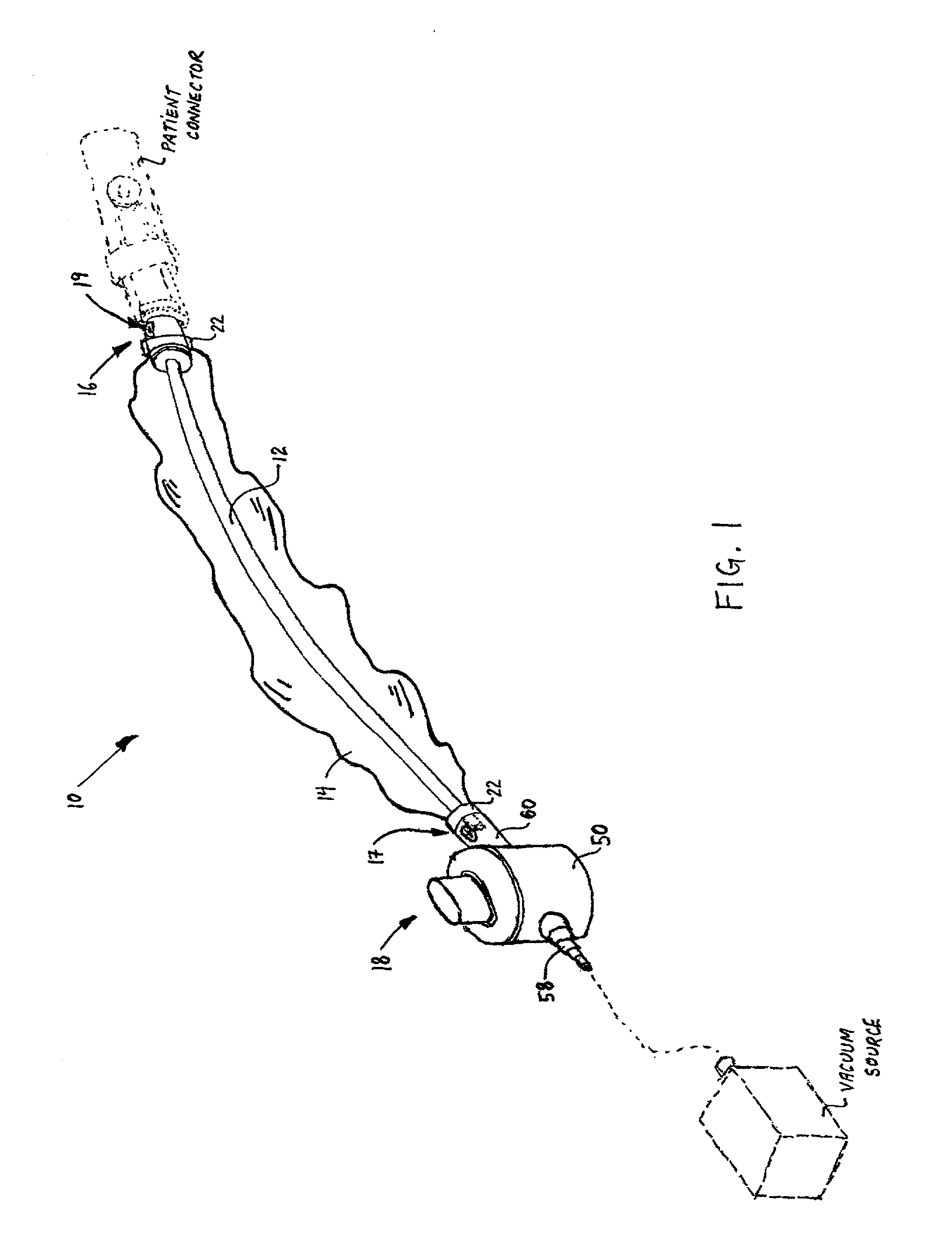
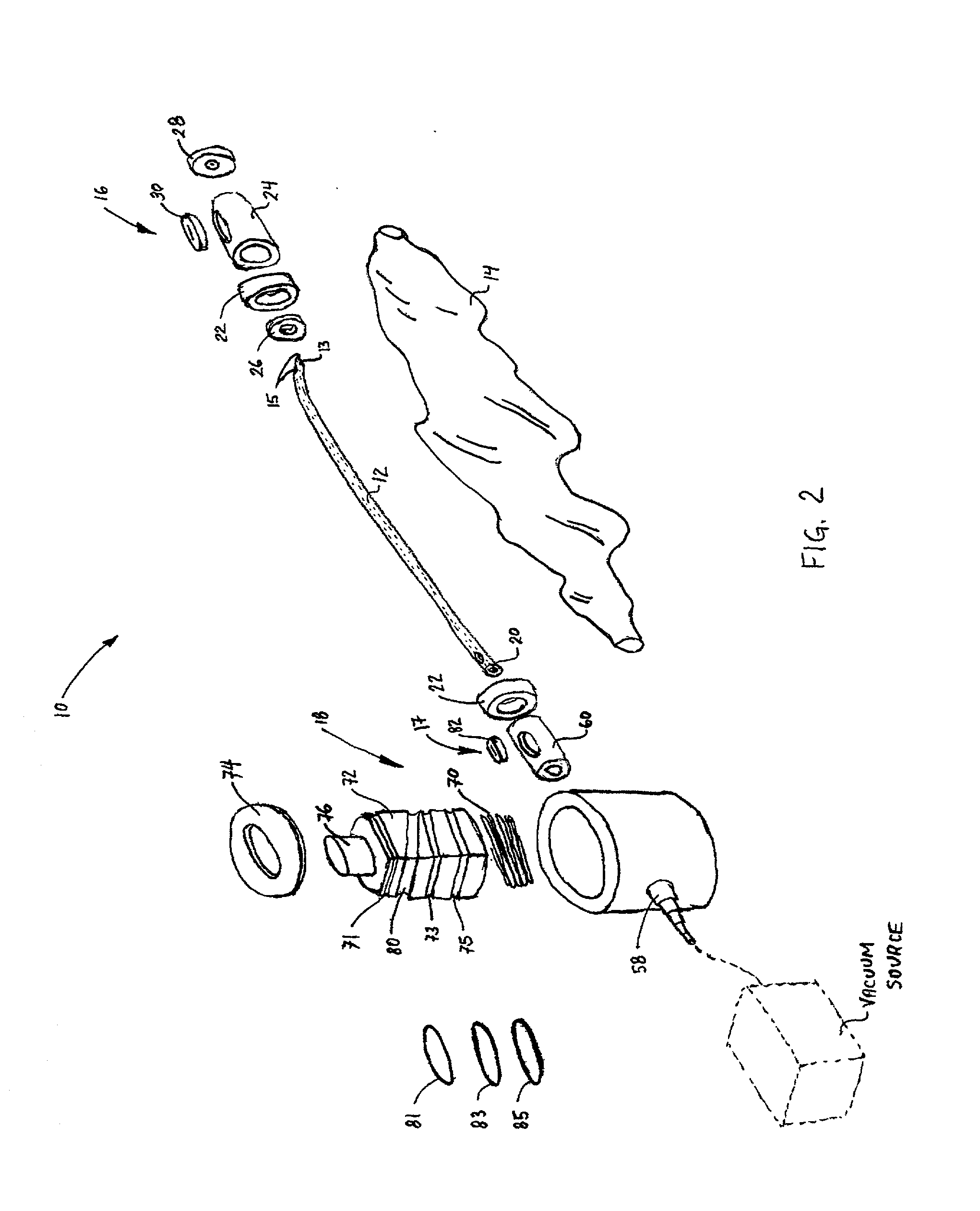
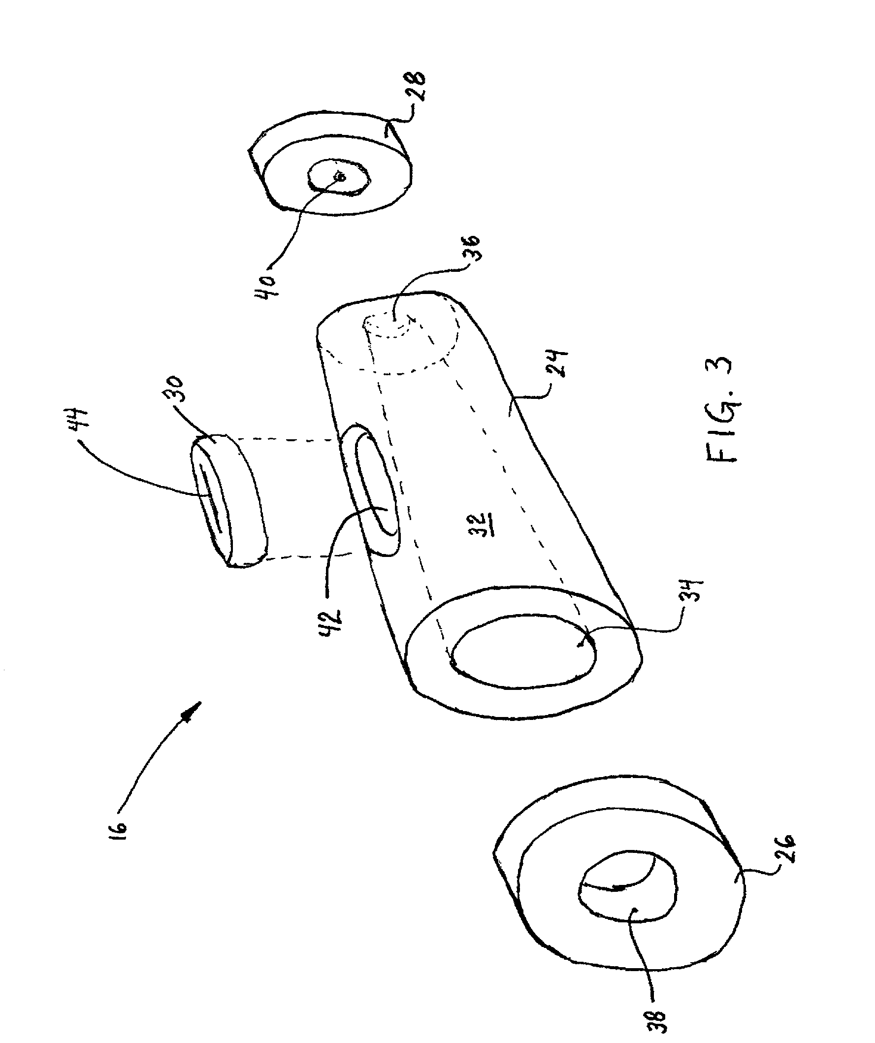
[0058] Referring to the drawings, the preferred embodiment of the closed catheter suction system of the present invention is illustrated and generally indicated as 10 in FIG. 1. Closed catheter suction system 10 comprises a flexible suction catheter 12 encased within a sheath 14 that is extendable between an adapter assembly 16 and a suction control valve 18. Adapter assembly 16 is attached to a patient connector (shown in phantom) while suction control valve 18 communicates with a vacuum source (shown in phantom) such that secretions can be aspirated from the patient through catheter 12 to the vacuum source for proper disposal. Closed catheter suction system 10 further includes a lavage port 17 located near the proximal end of catheter 12 for providing a means of introducing a lavage solution through catheter 12 during the aspiration procedure. A rinse port 19 is provided with adapter assembly 16 for the instillation of a rinse solution for cleansing catheter 12 of secretions after...


PUM


Abstract

The present invention relates to closed catheter suction systems used to aspirate secretions from the trachea of a patient and to rinse the catheter after such aspiration. The apparatus comprises a flexible suction catheter encased within a sheath that is fixed to a vacuum source at its proximal end and extendable through an adapter assembly at its distal end, near the patient. The adapter assembly connects the closed catheter suction system to a patient connector, and a suction control valve at the proximal end operates to aspirate secretions and to rinse the catheter. The closed catheter suction system also includes a lavage port and a rinse port, the latter of which is positioned near the distal end and is isolated from the ventilation circuit through the innovative use of a rinse chamber and a one-way valve. Advantageously, the lavage port is positioned near the proximal end, away from the patient, so as to prevent the accidental leakage of lavage into the ventilation circuit. Further, both the lavage port and the rinse port include a self-closing fill-valve that prevents the accidental loss of ventilator volume and which also prevents the discharge of infectious pathogens to the surrounding environment throughout the aspiration and rinse procedures.

Description

[0001] This application is based upon Provisional Patent Application, Serial No. 60 / 204,953, entitled "Integrated Respiratory / Ventilation System For Improved Patient Care", filed May 17, 2000, the contents of which are incorporated herein by reference in their entirety and continued preservation of which is requested.[0002] 1. Field of the Invention[0003] The present invention relates to devices and methods used in respiratory ventilation circuits, and more particularly to closed catheter suction systems which provide for aspiration of secretions from the passageway of a patient in addition to cleansing or rinsing of the catheter after the aspiration procedure is completed. More specifically, the present invention relates to closed catheter suction systems which are adapted for use with endotracheal or tracheal tubes for clearing secretions from the trachea of a patient.[0004] 2. Prior Art[0005] Known prior art closed catheter suction systems are largely used for insertion into cana...

Claims


Application Information

Patent Timeline
Patent Type & Authority Applications(United States)
IPC IPC(8): A61M16/04F16L37/23
CPCA61M16/0463A61M16/0465F16L37/23
Inventor ELKINS, JOHN I.
Owner ELKINS JOHN I
Learn More