Dielectric filter, antenna duplexer, and communications appliance
a technology of dielectric filters and duplexers, applied in the direction of coupling devices, electrical devices, waveguides, etc., can solve the problems of filter characteristic distortion, inability to meet the needs of users,
- Summary
- Abstract
- Description
- Claims
- Application Information
AI Technical Summary
Problems solved by technology
Method used
Image
Examples
first embodiment
[0250] (First Embodiment)
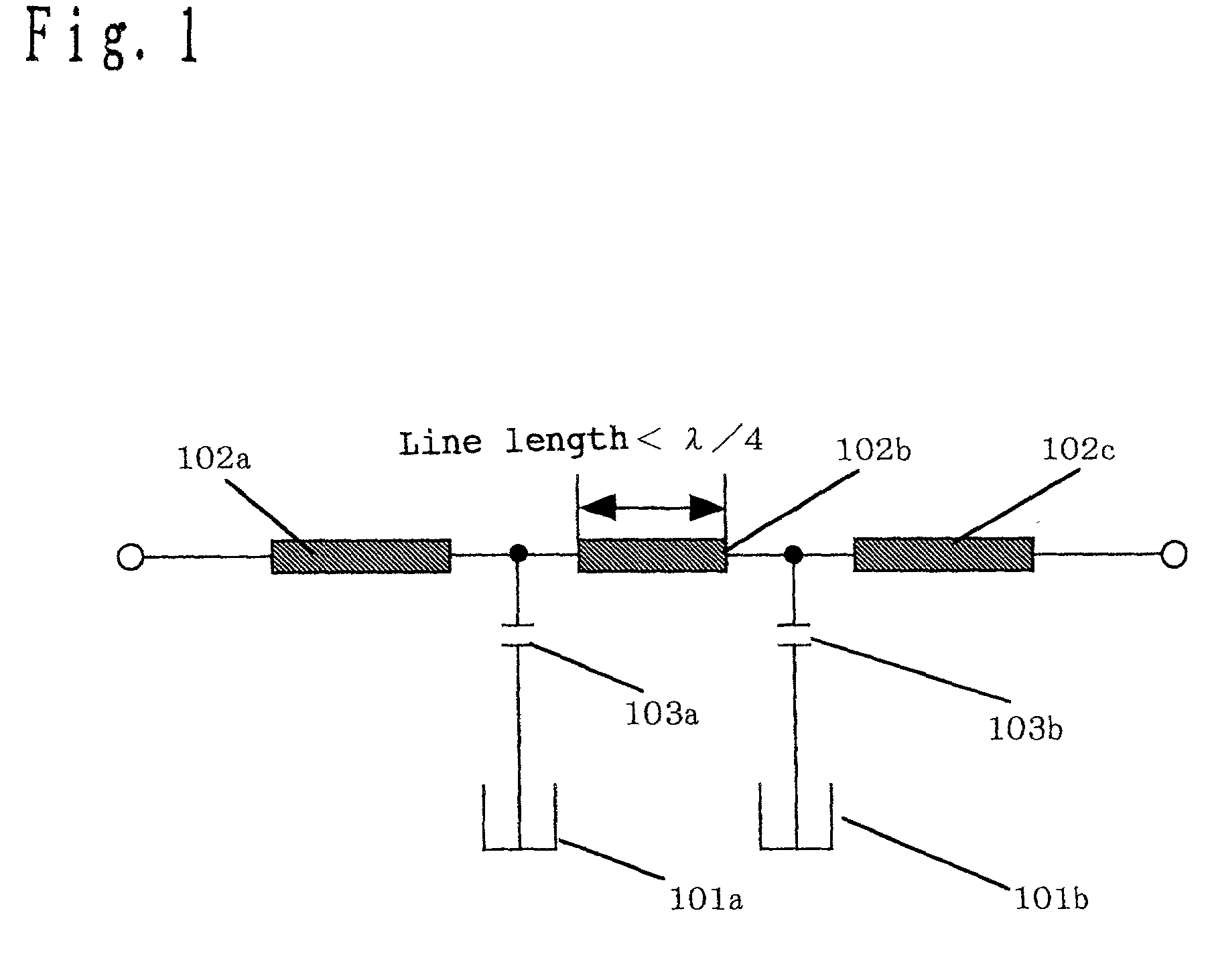
[0251] FIG. 1 shows an equivalent circuit of the filter according to a first embodiment of the present invention.
[0252] In FIG. 1, a filter forming a band rejection characteristic around the resonance frequency of a resonator is configured by a circuit in which a transmission line 102 having input / output terminals at both ends is connected to two resonators 101a and 101b respectively through capacitors 103a and 103b.
[0253] In FIG. 1, since the resonators 101a and 101b are connected parallel to the transmission line through the capacitors, the resonators 101a and 101b form an attenuation pole around the resonance frequency, and functions as a filter having a band rejection characteristic.
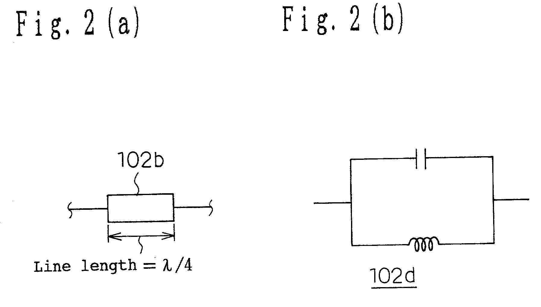
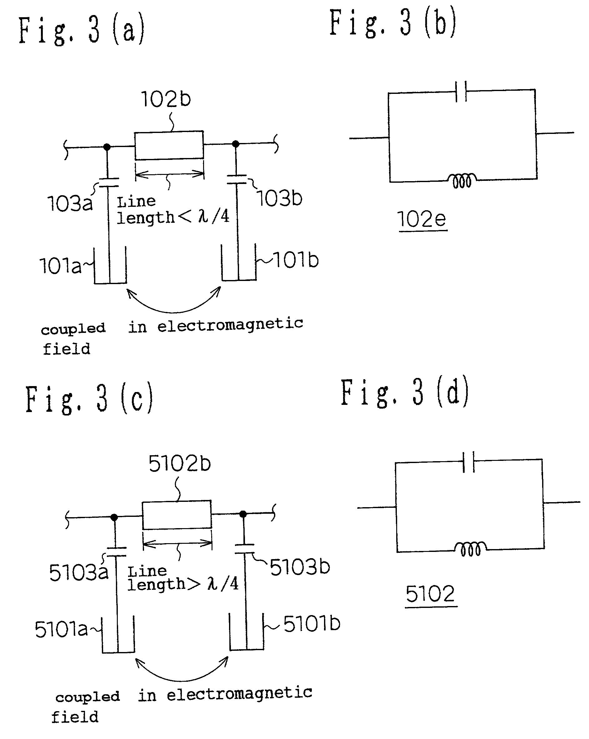
[0254] Conventionally, in the filter theory, it is necessary to have infinite impedance at the resonance frequency of a resonator to form a band rejection characteristic. To attain this, as shown in FIG. 2(a), the line length of the transmission line 102b is set as 1 / 4 of the...
second embodiment
[0258] (Second Embodiment)
[0259] FIG. 4 is a analytic oblique view of the dielectric filter having a layered structure according to a second embodiment of the present invention. FIG. 5 is a projection view of a resonator electrode and a transmission line electrode forming the dielectric filter in a layered structure. In FIG. 4, the dielectric filter according to the present embodiment has a first shield electrode 202 on the top surface of a first dielectric layer 201, a second dielectric layer 203 above the first shield electrode 202, resonator electrodes 204a and204b on the top surface of the second dielectric layer 203, a third dielectric layer 205 above the resonator electrodes 204a and 204b, a transmission line electrode 206 between input / output terminals on the top surface of the third dielectric layer 205, a fourth dielectric layer 207 above the transmission line electrode 206, a second shield electrode 208 on the top surface of the fourth dielectric layer 207, and a fifth die...
third embodiment
[0278] (Third Embodiment)
[0279] FIG. 13 is an analytic oblique view of the structure of the dielectric filter according to a third embodiment of the present invention. Since the present embodiment is basically the same as the second embodiment in structure, corresponding units are assigned the same numbers, and the detailed explanation is omitted here. According to the present embodiment, second resonator electrodes 212a and 212b are provided on the top surface of the fifth dielectric layer 209, a third resonator electrode 213a is connected to the second resonator electrode 212a, and a third resonator electrode 213b is connected to the second resonator electrode 212b. With the configuration, the resonance frequency can be adjusted by trimming the second resonator electrodes 212a and 212b using a luter, etc.
[0280] With the above mentioned configuration, in addition to the effect as a dielectric filter similar to that according to the second embodiment, an adjustable frequency range c...
PUM
 Abstract
Description
Claims
Application Information
 - R&D
- Intellectual Property
- Life Sciences
- Materials
- Tech Scout
- Unparalleled Data Quality
- Higher Quality Content
- 60% Fewer Hallucinations
Browse by: Latest US Patents, China's latest patents, Technical Efficacy Thesaurus, Application Domain, Technology Topic, Popular Technical Reports.
© 2025 PatSnap. All rights reserved.Legal|Privacy policy|Modern Slavery Act Transparency Statement|Sitemap|About US| Contact US: help@patsnap.com


