Non-invasive powerline communications system

a powerline communication and non-invasive technology, applied in powerline communications applications, frequency-division multiplexes, instruments, etc., can solve the problems of increased potential for outage and loss of the greatest number of customers, high repair costs of transformers and other equipment, and dangerous for utility company employees, etc., to achieve safe installation, easy installation, and low cost

Inactive Publication Date: 2001-12-20
FOSTER-MILLER
View PDF38 Cites 101 Cited by
  • Summary
  • Abstract
  • Description
  • Claims
  • Application Information

AI Technical Summary

Benefits of technology

[0009] It is a further object of this invention to provide such a non-invasive powerline communication system which is very easily, inexpensively and safely installed on the powerline.
[0012] This invention results from the realization that a truly simple, safe and inexpensive powerline communications system can be achieved by providing means for generating communication signals at a first location for transmission on a powerline, reactively coupling the generated communications signals to the powerline and receiving the communication signals at a second location.

Problems solved by technology

The potential for an outage and for loss of the greatest number of customers is increased during peak periods when power usage is at a maximum and delivery of continuous power is most critical.
Outages caused by faulty and overloaded lines, transformers and other equipment are expensive to repair, dangerous for utility company employees, and costly to the electric utility company in terms of income lost for lost service and in terms of damage to the utility's reputation.
This type of communication link is complex, expensive and requires use of a significant amount of hardware.
The direct electrical connection, however, requires that an invasive electrical connection be made to the power circuit that is being monitored.
This type of installation is expensive for the utility company as it requires a significant number of man hours to perform the installation, is potentially dangerous for the installer and can cause a service interruption for the customer.
Due to these limitations, powerline communications have not been widely used in the electric utility industry for communications with powerline sensors.

Method used


Image

  • Non-invasive powerline communications system
  • Non-invasive powerline communications system
  • Non-invasive powerline communications system

Examples


Embodiment Construction

[0019] Other objects, features and advantages will occur to those skilled in the art from the following description of a preferred embodiment and the accompanying drawings, in which:

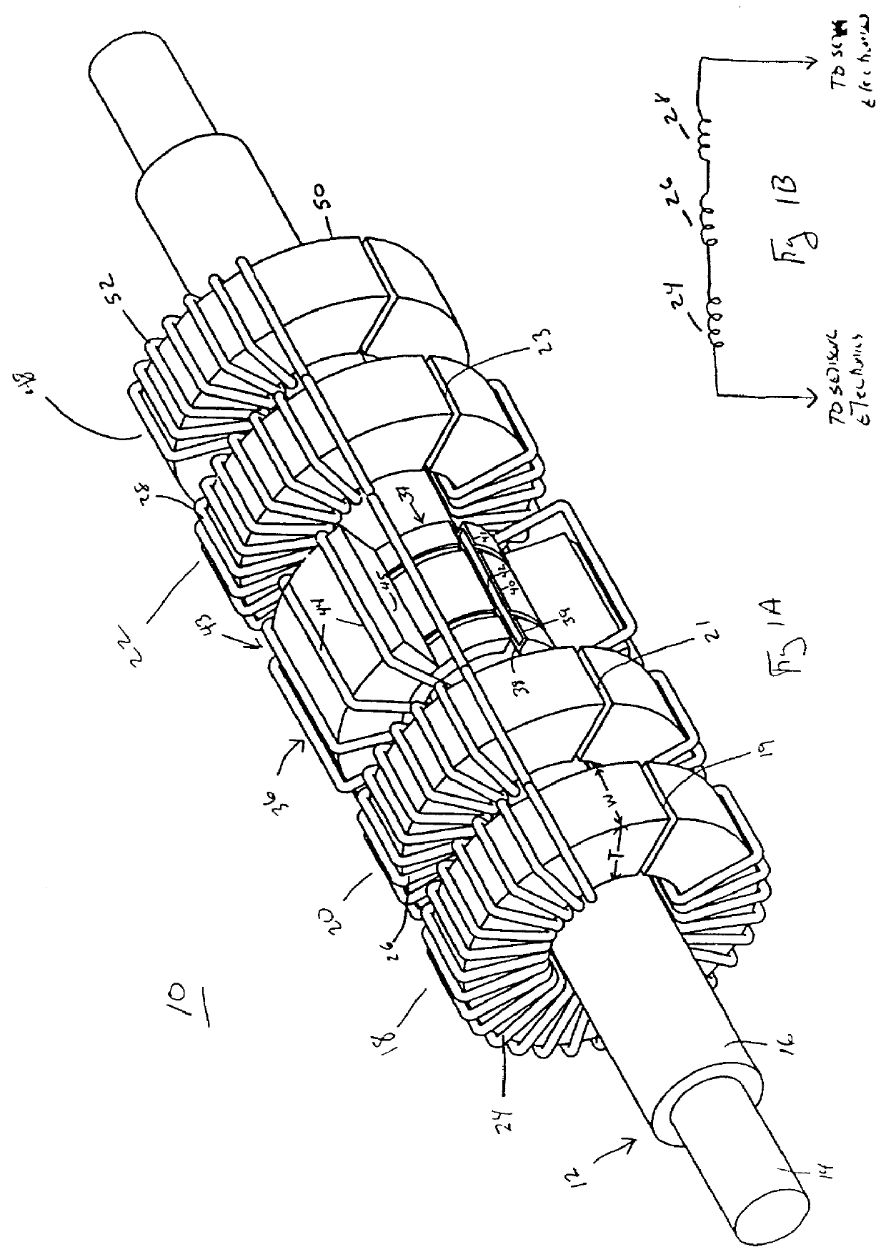
[0020] FIG. 1A is a three dimensional view of a modular core, self-powered powerline sensor according to this invention;

[0021] FIG. 1B is a schematic view depicting the interconnection of the windings about the modular core elements of FIG. 1;

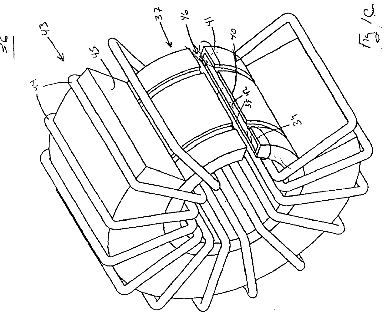
[0022] FIG. 1C is a three dimensional view of the sensing device of the modular core, self-powered powerline sensor as shown in FIG. 1A;

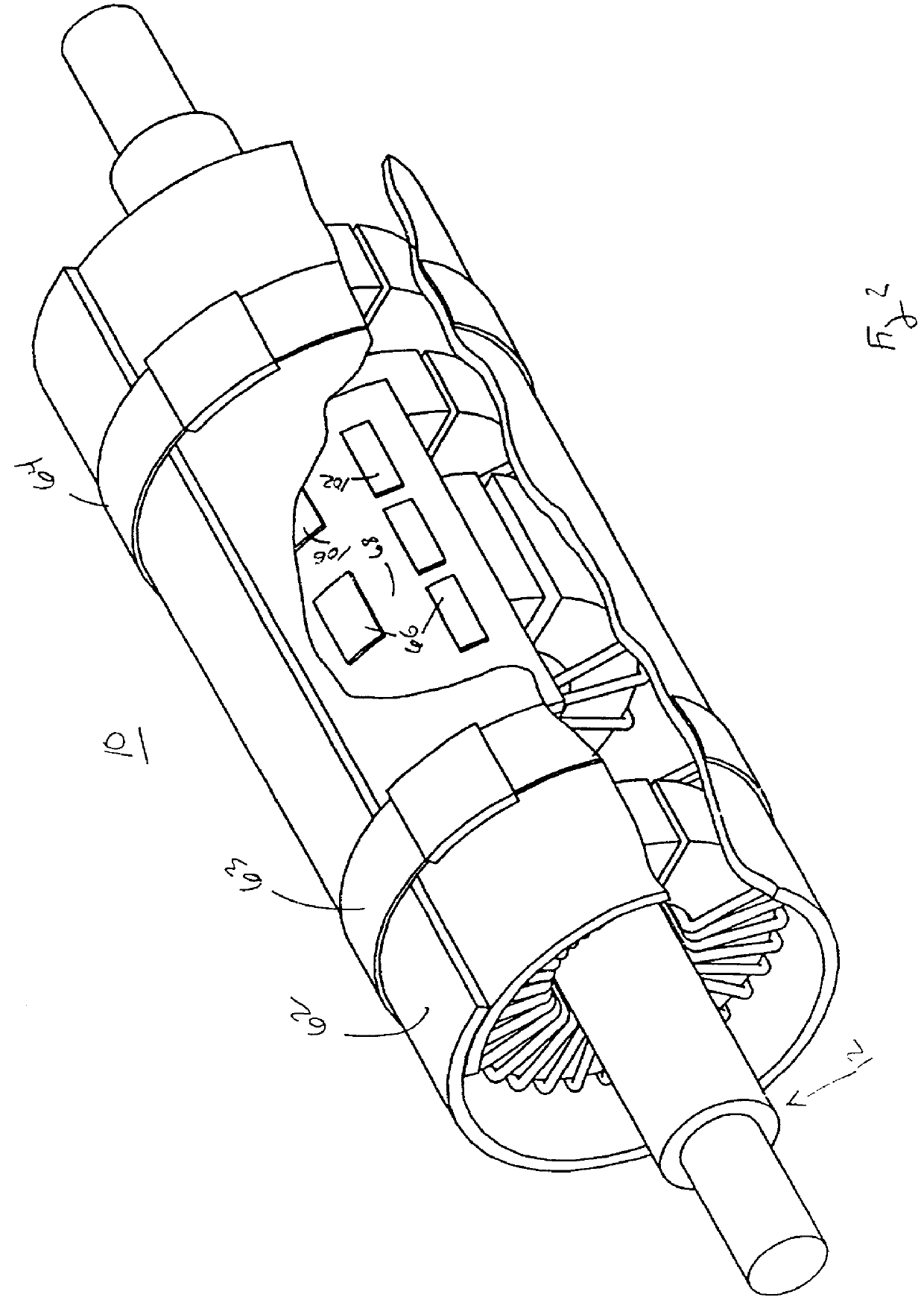
[0023] FIG. 2 depicts the modular core, self-powered powerline sensor of FIG. 1 with a protective covering wrapped thereabout and electronics components disposed between the protective covering and the windings of the sensor;

[0024] FIG. 3 is a schematic block diagram of the sensor of FIG. 1 and a base station both coupled to an a.c. powerline; and

[0025] FIG. 4 is a flow chart of the software that may be used by the microcontroller o...


PUM


Abstract

A non-invasive powerline communications system includes: means for generating communication signals at a first location for transmission on a powerline; means for reactively coupling the communication signals to the powerline; and means for receiving said communication signals at a second location.

Description

[0001] This invention relates to a powerline communication system and more particularly to such a system which couples communications signals between a communications device and a powerline in a completely non-invasive manner by reactively coupling the signals to and from the powerline.RELATED CASE[0002] This invention is a continuation-in-part application of the application entitled "MODULAR CORE, SELF-POWERED POWERLINE SENSOR" by the present inventors filed an even date herewith.BACKGROUND OF INVENTION[0003] Monitoring conditions in or about a.c. powerlines, in both overhead and underground and primary and secondary applications, is a useful practice for electric utility companies in order to anticipate outages which occur due to faulty equipment and overloads on a.c. powerlines and which result in loss of service for potentially a large number of customers. The potential for an outage and for loss of the greatest number of customers is increased during peak periods when power usa...

Claims


Application Information

Patent Timeline
Patent Type & Authority Applications(United States)
IPC IPC(8): G01R15/18G08C19/00H04B3/56
CPCH04B3/56H04B2203/5425H04B2203/5495H04B2203/5483H04B2203/5458
Inventor WIESMAN, RICHARD M.MASON, TIMOTHY J.BASTARACHE, GARY R.
Owner FOSTER-MILLER
Why Eureka
Try Eureka