Method of correcting thermal displacement of machine tool
a technology of machine tools and thermal displacement, which is applied in the direction of machine control, motor/generator/converter stoppers, process control, etc., can solve the problems of increasing machining time, affecting the structure or affecting the position of the sensor, etc., and achieves low cost and easy correction of thermal displacement.
- Summary
- Abstract
- Description
- Claims
- Application Information
AI Technical Summary
Benefits of technology
Problems solved by technology
Method used
Image
Examples
embodiments
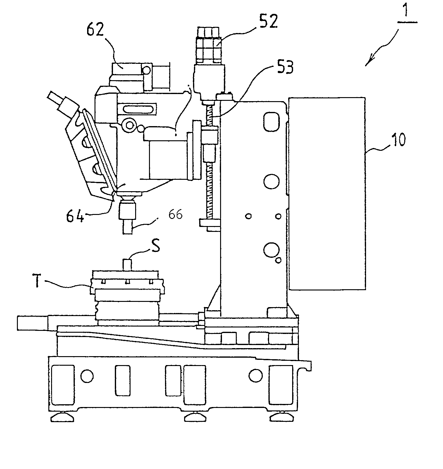
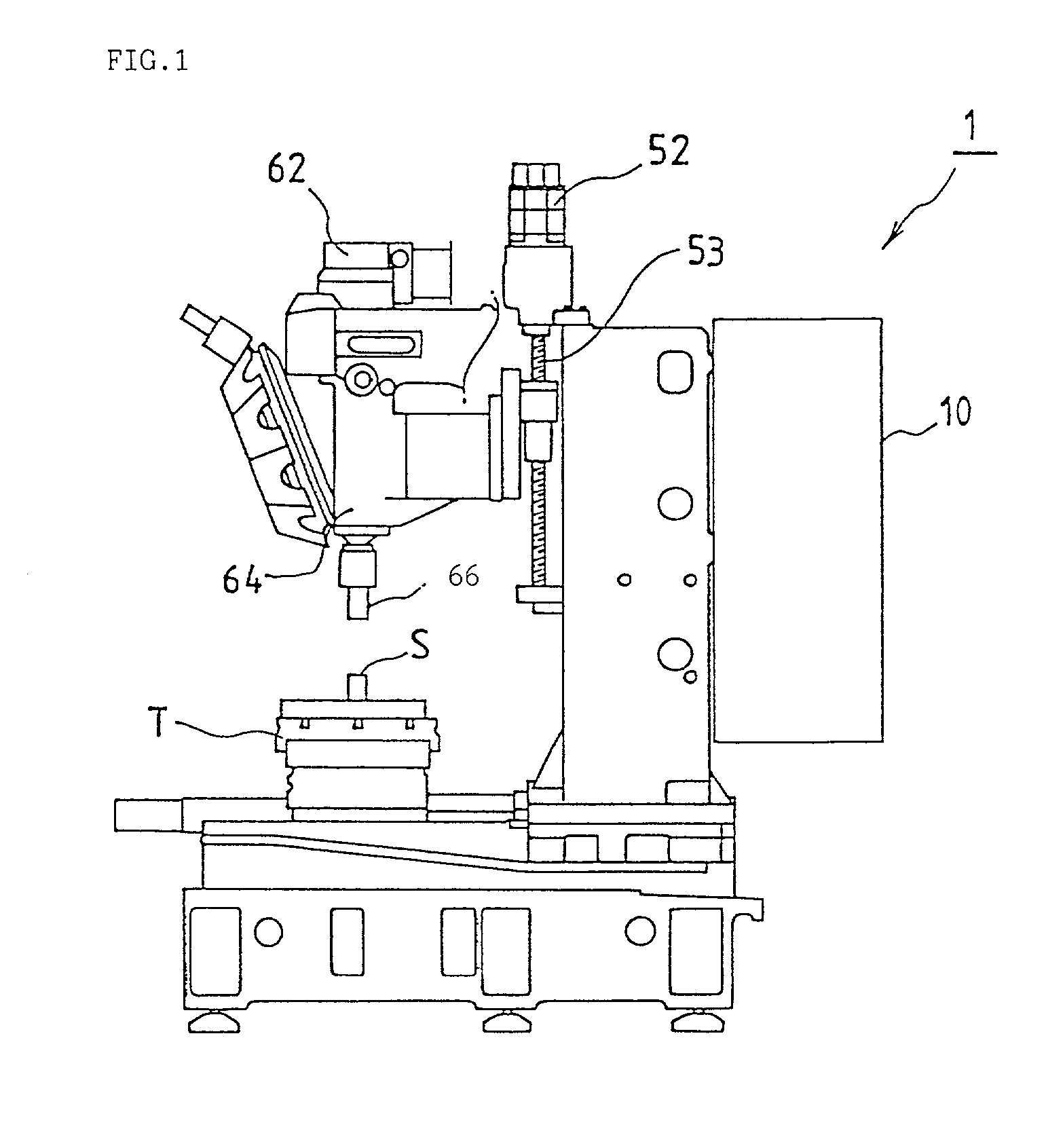
[0035] FIG. 1 is a schematic view of a vertical type drill press 1 of a machine tool to which the present invention is applied.
[0036] In FIG. 1, reference numeral 62 is a spindle motor, 52 is a servo motor for a Z shaft which is a vertical feed shaft, 10 is a numerical control device (CNC) which serves as a control device for controlling the drill press, 64 is a spindle, and 66 is a tool mounted to a spindle 64B. The table T is moved in directions of an X shaft and a Y shaft, which are orthogonal to the Z shaft and perpendicular to one another, by unillustrated servo motors for the X shaft and Y shaft. The structure of the drill press 1 is no different than conventional structures, and thus, further explanation thereof will be omitted.
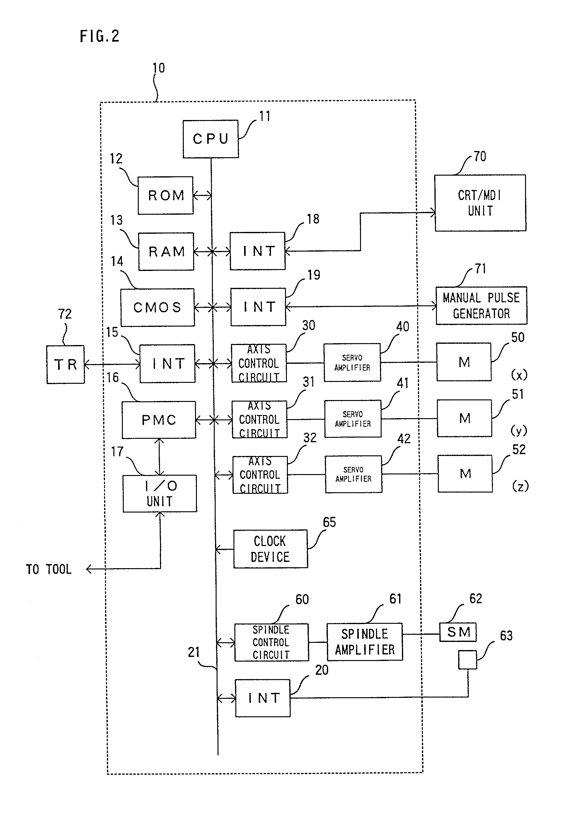
[0037] FIG. 2 is a functional block diagram showing main portions of the numerical control device 10 of the above-described drill press.
[0038] A processor 11 of the numerical control device 10 is a processor which overall controls the numerical control...
first embodiment
[0048] First, the present invention will be described.
[0049] In the present embodiment, thermal displacement, which arises from heat generation due to rotation of the spindle and from heat generation due to conduction of the heat generated by driving the spindle motor, is determined. In this case, as the thermal displacement of the spindle is expressed as a positional displacement of the Z axis, the thermal displacement of the spindle is determined by measuring the positional displacement of the Z axis.
[0050] In the measurement of the thermal displacement, the spindle motor is rotated at a predetermined rotational speed, and each time a predetermined interval of time passes, the height of the displacement measuring apparatus is adjusted, and the distal end operation surface of the tool is made to contact from the direction of Z axis, and the thermal displacement of the spindle is thereby measured. As for the measurement data, a plurality of types of data can be determined by changin...
second embodiment
[0069] Next, the present invention will be described.
[0070] In the present embodiment, the entire stroke of the feed shaft is divided into a finite number of sections, and thermal displacement correction for the feed shafts is carried out by using the thermal displacement for each of the divisional sections.
[0071] FIG. 5 is a schematic diagram for explaining the divisional sections of the feed shaft. In FIG. 5, the entire stroke of the feed shaft is divided into X+1 sections, from a section O (a section adjacent to a reference position) to a section X (the section the furthest from the reference position).
[0072] The thermal displacement .delta..sub.nI of a section I at a time n is expressed by the following equation.
.delta..sub.nI=.delta..sub.(n-1)I+A3.sub.nI-B3.sub.nI+D.sub.nI (8)
[0073] wherein
D.sub.nI=k5.multidot.{.delta..sub.(n-1)I+1+.delta..sub.(n-1)I-1-2.multidot-..delta..sub.(n-1)I} (9)
[0074] Here, with n as the sampling time,
[0075] .delta..sub.nI: thermal displacement of sect...
PUM
| Property | Measurement | Unit |
|---|---|---|
| Speed | aaaaa | aaaaa |
| Displacement | aaaaa | aaaaa |
Abstract
Description
Claims
Application Information
 - R&D
- Intellectual Property
- Life Sciences
- Materials
- Tech Scout
- Unparalleled Data Quality
- Higher Quality Content
- 60% Fewer Hallucinations
Browse by: Latest US Patents, China's latest patents, Technical Efficacy Thesaurus, Application Domain, Technology Topic, Popular Technical Reports.
© 2025 PatSnap. All rights reserved.Legal|Privacy policy|Modern Slavery Act Transparency Statement|Sitemap|About US| Contact US: help@patsnap.com


