Valve seat and valve

Inactive Publication Date: 2002-02-28
MEDTRONIC INC
View PDF0 Cites 41 Cited by
  • Summary
  • Abstract
  • Description
  • Claims
  • Application Information

AI Technical Summary

Problems solved by technology

Although such drainage systems have provided successful results, a problem of overdrainage of the cerebrospinal fluid from the brain ventricles sometimes exists.
Overdrainage of cerebrospinal fluid may result in excessive reduction of the cerebrospinal fluid pressure within the brain ventricles and predispose the development of a subdural hematoma or hydroma, and excessive reduction of ventricular size leading to shunt obstruction because of impingement of the ve

Method used


Image

  • Valve seat and valve
  • Valve seat and valve
  • Valve seat and valve

Examples


Embodiment Construction

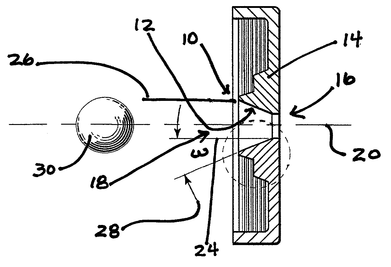
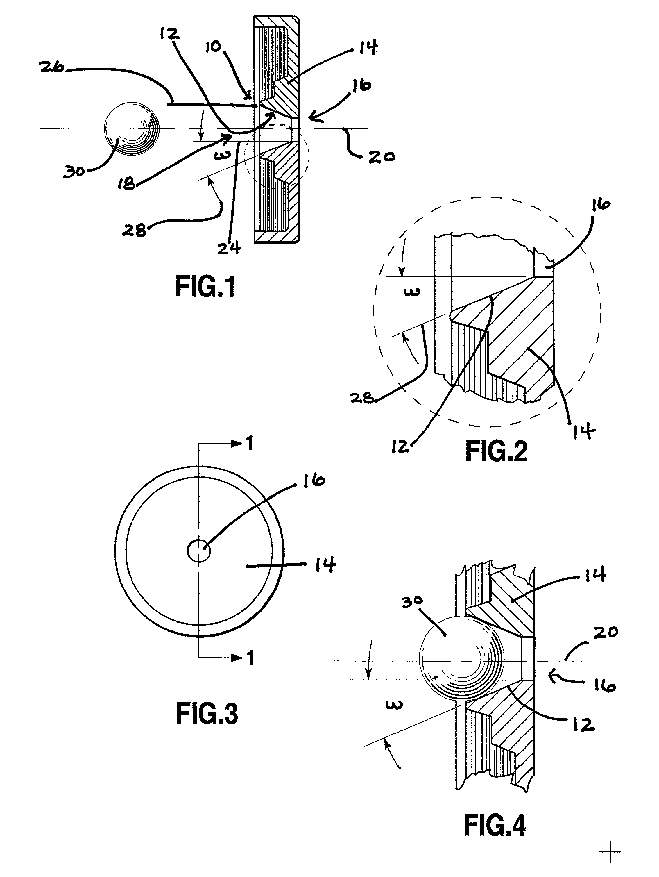
[0033] FIGS. 1-4 show a valve seat generally labeled 10. Valve seat 10 is defined by a conical wall 12 formed in a manifold 14 between a narrow circular opening 16 and a wide circular opening 18. A central axis 20 passes through the center of both the narrow circular opening 16 and the wide circular opening 18.

[0034] Narrow circular opening 16 is formed at the narrow end of valve seat 10 and wide circular opening 18 is formed at the wider end of valve seat 10. The radius of narrow circular opening 16 is equal to the distance from the central axis 20 to line 24 spaced from central axis 20. Wide circular opening 18 is formed at the wider end of valve seat 10. The radius of wide circular opening 18 is equal to the distance from the central axis 20 to a line 26 spaced from central axis 20.

[0035] As stated above, wall 12 is conical. Wall 12 is formed by rotating a line 28 that intersects central axis 20 around central axis 20. Line 28 intersects central axis 20 at an angle .omega.. The a...


PUM


Abstract

A valve seat for a ball valve in an adjustable medical valve is described. The valve seat is formed as a cone in a manifold. The cone is formed by rotating a line that intersects a central axis of the valve seat around the central axis. The angle of the intersection between the line and the central axis is doubled to form the included angle of the valve seat. Generally, the narrower the included angle, the better the tolerance of the assembled valve for variations in the spring constant of the pressure regulating spring. Specifically, the present invention has included angles between 0 and 90 degrees with the preferred included angles being between 10 and 40 degrees. A valve embodying the valve seat is also disclosed.

Description

[0001] 1. Field of the Invention[0002] This invention relates generally to surgically implanted physiological shunt systems and related flow control devices. More particularly, the present invention relates to a valve seat in a one-way flow control valve for controlling the flow of cerebrospinal fluid out of a brain ventricle and preventing backflow of fluid into the brain ventricle.[0003] 2. Description of Related Art[0004] In the medical arts, to relieve undesirable accumulation of fluids it is frequently necessary to provide a means for draining a fluid from one part of the human body to another in a controlled manner. This is required, for example, in the treatment of hydrocephalus, an ailment usually afflicting infants or children in which fluids accumulate within the skull and exert extreme pressure and skull deforming forces.[0005] In treating hydrocephalus, cerebrospinal fluid accumulated in the brain ventricles is typically drained away utilizing a drainage or shunt system ...

Claims


Application Information

Patent Timeline
IPC IPC(8): A61M27/00A61M39/24
CPCA61M27/006A61M39/24
Inventor BERTRAND, WILLIAM JEFFHAMLEN, ROBERT CUSHINGMAY, STEVE J.SOLIS, MITCHELL ANDREW
Owner MEDTRONIC INC
Why Eureka
Try Eureka