Fuel cell system having cooling apparatus

a fuel cell and cooling device technology, applied in the direction of fuel cells, fuel cell details, electrical devices, etc., can solve the problems of difficulty in maintaining a sufficiently high level of insulation of the fuel cell system in some cases for the aforementioned prior art cooling apparatus

Inactive Publication Date: 2002-03-14
TOYOTA JIDOSHA KK
View PDF0 Cites 25 Cited by
  • Summary
  • Abstract
  • Description
  • Claims
  • Application Information

AI Technical Summary

Problems solved by technology

However, since the antifreezing solution containing water and ethylene glycol is capable of conducting electricity, it is difficult f...

Method used


Image

  • Fuel cell system having cooling apparatus
  • Fuel cell system having cooling apparatus
  • Fuel cell system having cooling apparatus

Examples


first embodiment

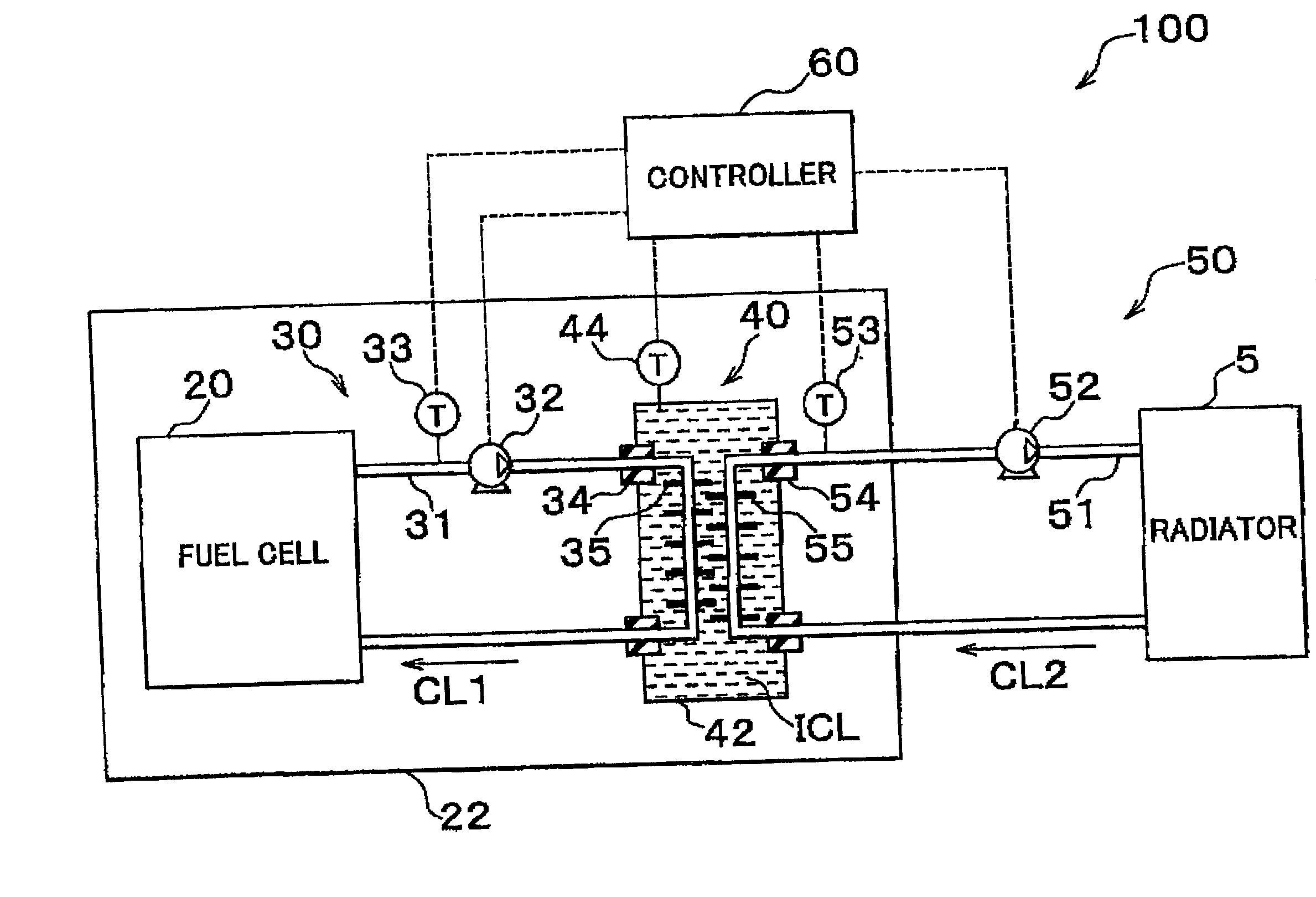
[0041] In the fuel cell system 100 of the first embodiment, the two forced circulation cooling systems 30, 50 are provided independently of each other, and the intermediate cooling system 40 employing the insulating coolant ICL is interposed between the two cooling systems 30, 50 as described above. Therefore, high electric insulation can be achieved.

second embodiment

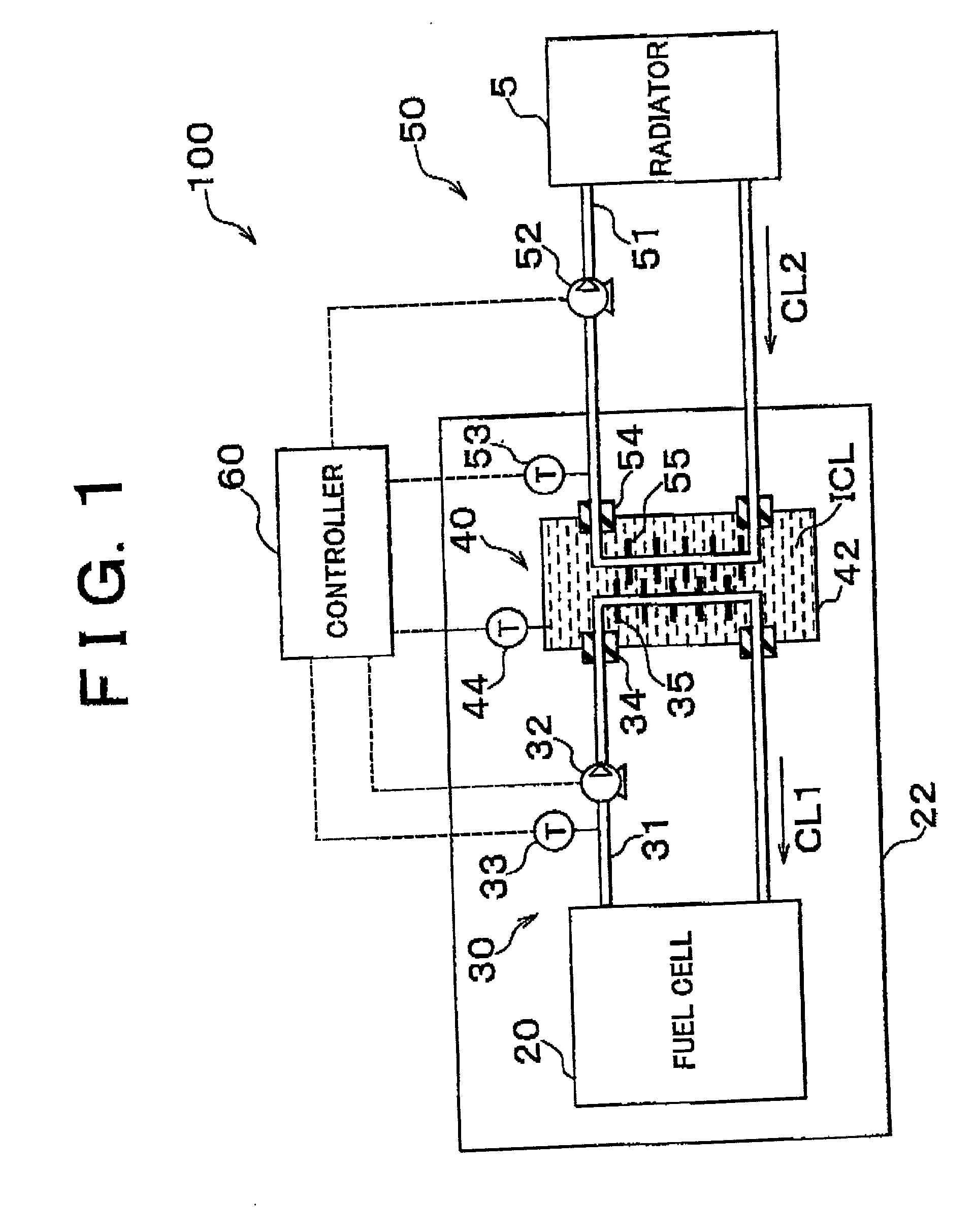
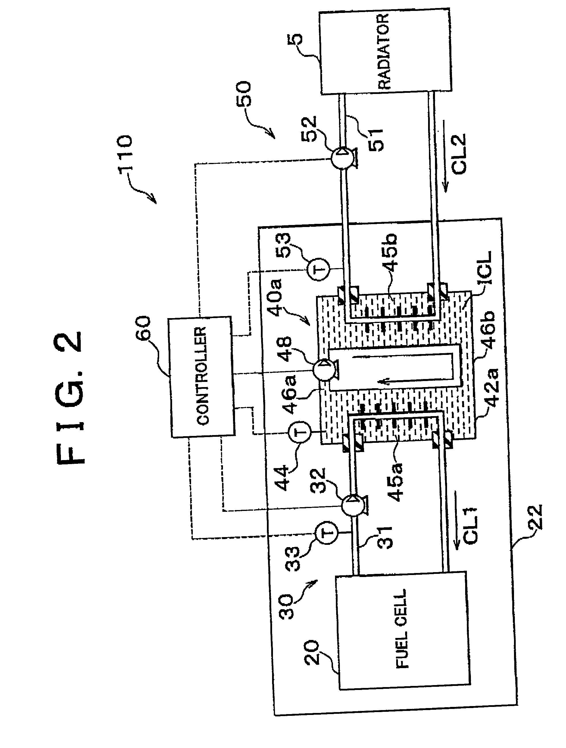
[0042] SECOND EMBODIMENT

[0043] FIG. 2 is a schematic diagram illustrating a construction of a fuel cell system 110 of a second embodiment of the invention. The fuel cell system 110 differs from the system of the first embodiment merely in an intermediate cooling system. Other arrangements of the second embodiment are substantially the same as those of the first embodiment. A container 42a of an intermediate cooling system 40a in the second embodiment has a first heat exchange chamber 45a in which a circulation passage 31 of a first forced circulation cooling system 30 extends, and a second heat exchange chamber 45b in which a circulation passage 51 of a second forced circulation cooling system 50 extends. The first heat exchange chamber 45a and the second heat exchange chamber 45b are interconnected via piping portions 46a, 46b. Of the two piping portions 46a, 46b, the piping portion 46a is provided with a pump 48. When the pump 48 is operated, an insulating coolant ICL is forced to...

third embodiment

[0045] THIRD EMBODIMENT

[0046] FIG. 3 is a diagram illustrating a construction of a fuel cell system 120 of a third embodiment of the invention. Unlike the systems of the first and second embodiments, the fuel cell system 120 of the third embodiment does not have either an intermediate cooling system or a second forced circulation cooling system, but merely has a first forced circulation cooling system 30a.

[0047] The first forced circulation cooling system 30a has a radiator 15, and a metal-made pipe 31 a that constitutes a circulation passage for circulation between the radiator 15 and a fuel cell 20. The pipe 31a is provided with a pump 32 and a temperature sensor 33. Joints 80 formed from an insulating material are provided between the fuel cell 20 and the pipe 31a. As a coolant, an insulating coolant ICL as described above in conjunction with the first embodiment is employed. If the pipe 31a is formed from an insulating material, the insulating joints 80 are not needed.

[0048] In ...


PUM


Abstract

A cooling apparatus that cools a fuel cell has a first forced circulation cooling system that directly cools the fuel cell, a second forced circulation cooling system that is independent of the first forced circulation cooling system, and an intermediate cooling system that exchanges heat with each of the first and second forced circulation cooling systems. A container provided in the intermediate cooling system contains an electrically insulating liquid as a coolant.

Description

INCORPORATION BY REFERENCE[0001] The disclosure of Japanese Patent Application No. 2000-213910 filed on Jul. 14, 2000 including the specification, drawings and abstract is incorporated herein by reference in its entirety.[0002] 1. Field of the Invention[0003] The invention relates to a technology for cooling a fuel cell in a fuel cell system.[0004] 2. Description of the Related Art[0005] Fuel cells that generate electric power by utilizing an electrochemical reaction between hydrogen and oxygen are expected as a next-generation energy source. During operation (power generation) of a fuel cell, a considerable amount of heat is produced by the electrochemical reaction. Therefore, an ordinary fuel cell system has a cooling apparatus for cooling the fuel cell.[0006] Japanese Patent Application Laid-Open No. 8-184877, for example, describes a cooling apparatus of a fuel cell system. In this apparatus, the fuel cell is cooled through the use of a coolant that includes an antifreezing solu...

Claims


Application Information

Patent Timeline
IPC IPC(8): H01M8/02H01M8/04
CPCH01M8/04029Y02E60/50
Inventor ISHIKAWA, TETSUHIRO
Owner TOYOTA JIDOSHA KK
Why Eureka
Try Eureka