
Leading edge channel for enhancement of lift/drag ratio and reduction of sonic boom

a leading edge channel and lift/drag technology, applied in the field of supersonic or hypersonic body sections, can solve the problems of increasing fuel expenses, affecting the performance of aircraft,

Inactive Publication Date: 2002-04-18
GEORGIA TECH RES CORP
View PDF0 Cites 5 Cited by
  • Summary
  • Abstract
  • Description
  • Claims
  • Application Information

AI Technical Summary

Problems solved by technology

However, existing supersonic and hypersonic technology suffers from several drawbacks.
For example, aerodynamic drag is substantial at supersonic and hypersonic speeds, and adds significantly to fuel expenses.
Also, noise due to sonic booms has been found objectionable, in particular, by those living under flight paths and near airports.
These vehicles are similar in that their range, payload mass fractions and economic feasibility are extremely sensitive to aerodynamic drag.
Proposed hypersonic vehicles such as the National Aerospace Plane and X-30 have not advanced due, in part, to diminishing projected payload margins and concerns regarding airbreathing engine capabilities.
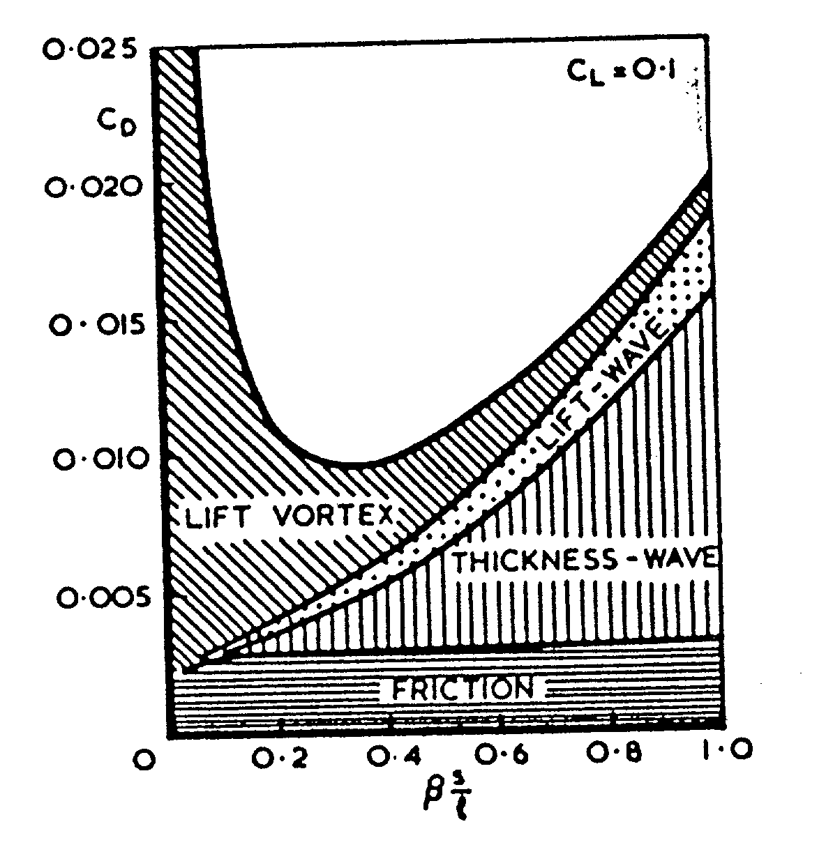
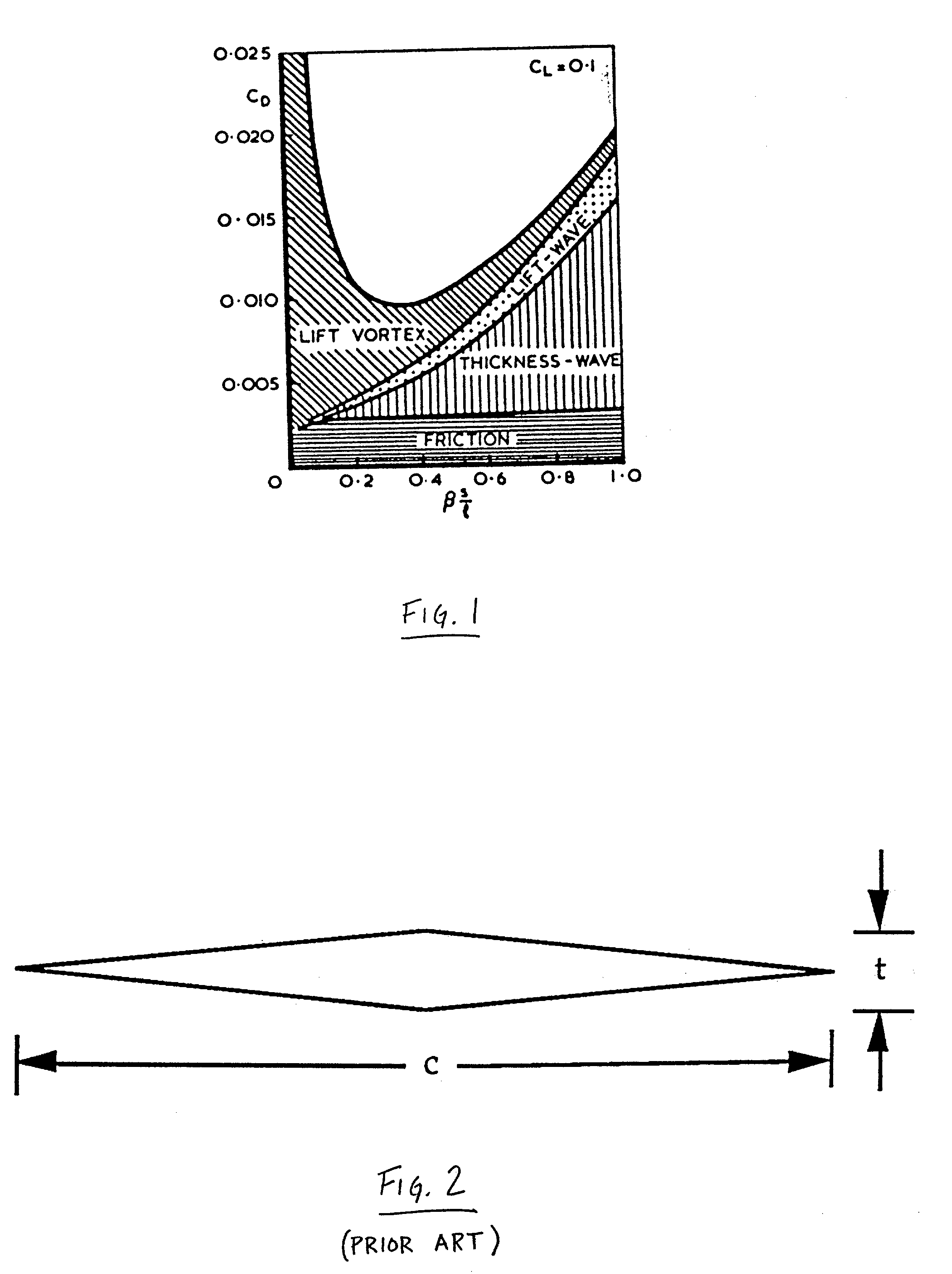
It should be noted that vehicles with s / l lower than approximately 0.2 (i.e. vehicles whose wings are extremely swept) are impractical due to excessive required runway lengths.
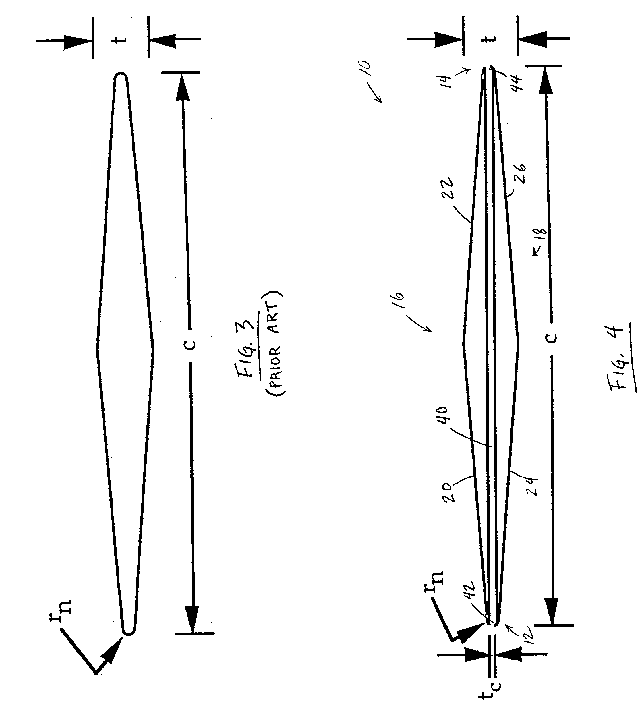
However, very sharp leading edges are not practical for a number of reasons: (1) very sharp leading edges are difficult and expensive to manufacture; (2) some blunting is required for structural strength; (3) the flow over wings with sharp leading edges is very susceptible to separation even at low angles of attack and flight speeds; and (4) the heat transfer to sharp leading edges at high supersonic Mach numbers is severe.
The heat transfer to such vehicles is most severe at stagnation points which occur on the leading edges and nose of the vehicle.
Thus, sharp leading edges (i.e., r.sub.n=0) experience extreme heat transfer, which may melt or otherwise damage the component.
However, much of the wave drag experienced by these vehicles is due to leading edge blunting.
However, a blunted leading edge results in higher drag at supersonic cruise conditions relative to a wing with a sharp leading edge.
Sonic boom has also been found to limit the application of supersonic and hypersonic transport.
However, for sharp-nosed vehicles, subsequent compressions around the vehicle tend to be strong and coalesce at mid-field and far-field into a much stronger over-pressure relative to a blunt nose geometry.
Significantly blunted supersonic cruise vehicles have not been utilized, however, because the wave drag of such vehicles becomes unreasonably high.
However this technique suffers the disadvantage that it requires that significant power be supplied from the engines to pump the flow against a supersonic freestream.

Method used


Image

  • Leading edge channel for enhancement of lift/drag ratio and reduction of sonic boom
  • Leading edge channel for enhancement of lift/drag ratio and reduction of sonic boom
  • Leading edge channel for enhancement of lift/drag ratio and reduction of sonic boom

Examples


first embodiment

[0079] For certain applications, as described in greater detail below, it has been found desirable to provide an aerodynamic body with a passive airflow channel which can be selectively opened and closed depending upon the flight conditions. FIGS. 29-31 show several closure mechanisms 100 for enabling selective opening and closure of the channel 40 at the leading edge 12 of an aerodynamic body. FIGS. 29a and 29b show the opened and closed configurations, respectively, of a closure mechanism 100. This embodiment of the closure mechanism 100 generally comprises a flat plate 102 hingedly connected to the lower nose portion of the aerodynamic body, adjacent the entrance to channel 40, by means of a hinge 104. Actuating means 106, such as a hydraulic or pneumatic cylinder, are provided between the aerodynamic body and the plate 102 for moving plate 102 between the channel open (FIG. 29a) and channel closed (FIG. 29b) positions.

second embodiment

[0080] the closure mechanism 100 is shown in its opened and closed positions by FIGS. 30a and 30b, respectively. This embodiment of the closure mechanism comprises an angled closure gate 110, hingedly connected to the aerodynamic body by means of a hinge 104. Actuating means (unshown) are provided for moving the angled closure gate 110 between its opened and closed configurations. The portion of the angled closure gate 110 which blocks the channel 40 in the closed configuration can be curved to generally match the contour of the leading edge 12 of the aerodynamic body.

[0081] A further embodiment of a closure mechanism 100 is shown in its opened and closed positions by FIGS. 31a and 31b, respectively. In this embodiment, a rotating closure element 115 is pivotally mounted adjacent the leading edge 12 of the aerodynamic body. The rotating closure element 115 is preferably generally cylindrical, having a slot 117 provided through its central portion. A section of flexible duct 119 can ...


PUM


Abstract

The leading edges of wings, nose assemblies, tails, fins, struts, and other components of aircraft, atmospheric entry vehicles and missiles in which the leading edge is blunted and the flight Mach number is supersonic, are provided with passive airflow channel, resulting in significantly reduced wave drag and total drag, significantly increased lift-to-drag ratio, and reduced sonic boom.

Description

[0001] 1. Field of the Invention[0002] The present invention relates generally to the field of supersonic aeronautics, and relates more specifically to a novel supersonic or hypersonic body section design incorporating one or more hollow channels in the body section that allow freestream air to flow through the channel(s) resulting in reduced drag and sonic boom.[0003] 2. Description of Related Art[0004] A variety of supersonic and hypersonic vehicles are currently being studied for commercial and military applications. However, existing supersonic and hypersonic technology suffers from several drawbacks. For example, aerodynamic drag is substantial at supersonic and hypersonic speeds, and adds significantly to fuel expenses. Also, noise due to sonic booms has been found objectionable, in particular, by those living under flight paths and near airports.[0005] The advantages of supersonic and hypersonic transport, however, justify continued research and development directed to overco...

Claims


Application Information

Patent Timeline
IPC IPC(8): B64C3/14B64C30/00
CPCB64C3/14Y02T50/12B64C2003/143B64C30/00Y02T50/10
Inventor RUFFIN, STEPHEN M.
Owner GEORGIA TECH RES CORP
Learn More