
Phase-linear wide band frequency conversion

a frequency conversion and phase-linear technology, applied in the field of phase-linear wide band frequency conversion, can solve the problems of insufficient attenuation of lo signal, increased filtering difficulty, unwanted image frequency band,

Inactive Publication Date: 2002-04-25
ALCATEL LUCENT SAS
View PDF13 Cites 17 Cited by
  • Summary
  • Abstract
  • Description
  • Claims
  • Application Information

AI Technical Summary

Problems solved by technology

Both the local oscillator and the image frequency signals can more or less effectively be suppressed by filtering, but the filtering becomes more difficult the broader is the frequency band to be converted.
However, there is some times a main problem that the LO signal is not sufficiently attenuated, together with the requirement for an effective suppression of the unwanted sideband.
By down-conversion the main problem is the unwanted image frequency band, resulting from the mixing between the LO signal and signals appearing in the opposite sideband.
Traditionally the stringent requirements for phase and level balance, however, have been regarded as a hindering bar for moderate to broad band circuit design.
One requirement is the need for very steep filters at BB; filters that easily become bulky and complicated, particularly when based upon LC components.
Although the I / Q or quadrature method in the principle seems to be the ideal form for transposing a frequency spectrum, there have been a number of practical limitations.
I / Q signal processing can be carried out in passive circuits, but such circuits tend to have very limited bandwidth and are far from phase linear.
However, new problems and disadvantages are likely to appear, particularly those related to aliasing.
If further the signals to be converted are non-digital in the first place, solutions using analogue to digital converters (ADC) will be fairly complicated, even at limited bandwidths.
An expansion into higher frequencies further complicates the situation due to the need for RF filtering and / or lack of tunability.
Without the use of I / Q technique the conventional way to use step-wise frequency conversion (i.a. known from double-superheterodyne receivers) could be tried, but such solutions tend to be rather complicated and will often suffer from drawbacks with respect to performance.
A direct conversion using a subsequent advanced filtering at RF can be used in some cases but is rather limited when it comes to the possibility for tuning and adaptation.
Additionally the device could be supplied with feedback loops to further improve the balance, even if such additional circuits easily could make the unit rather complex.

Method used


Image

  • Phase-linear wide band frequency conversion
  • Phase-linear wide band frequency conversion
  • Phase-linear wide band frequency conversion

Examples


Embodiment Construction

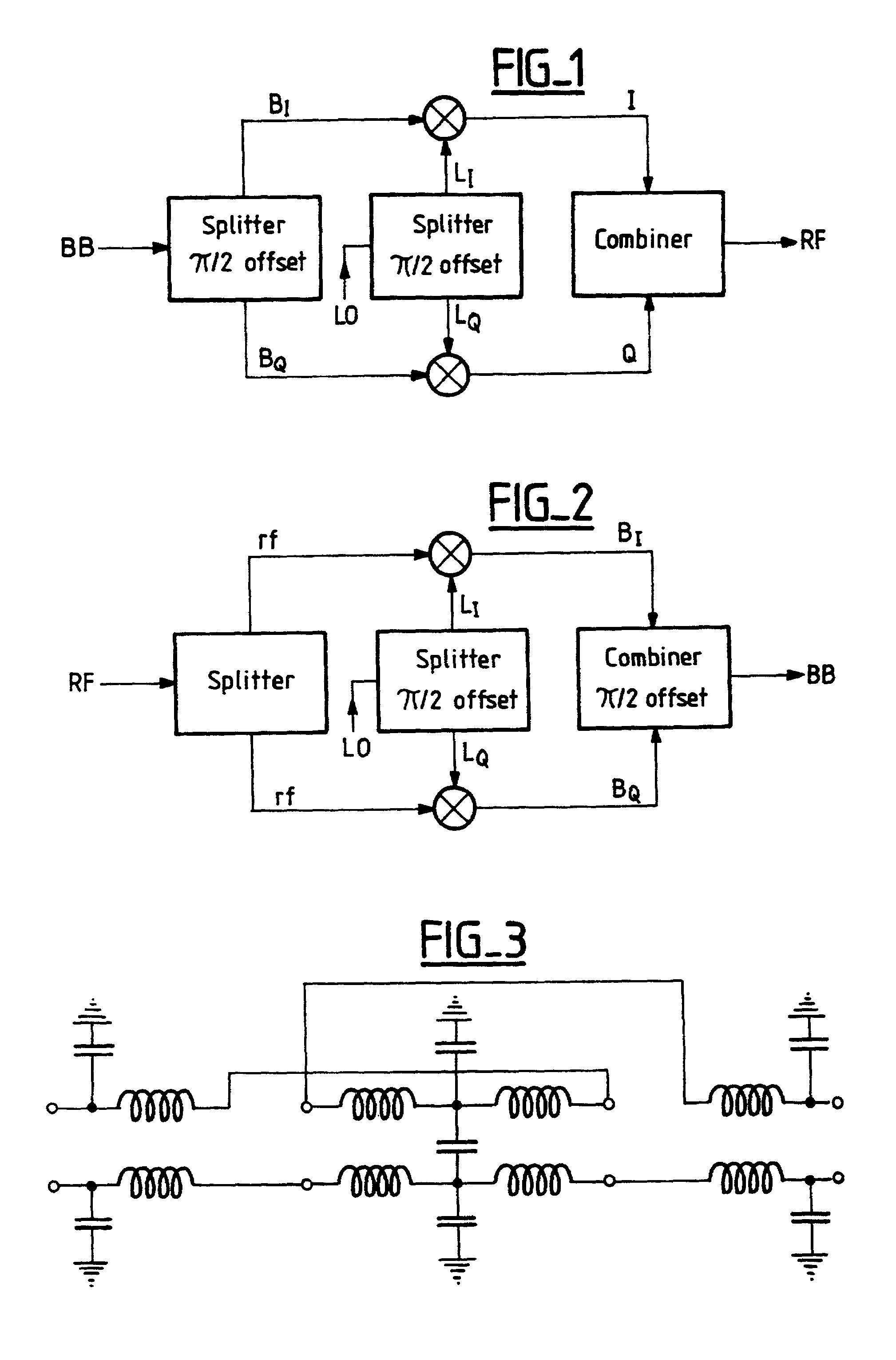
[0089] FIG. 1 of the drawings illustrates the prior art principle used by up-converting a baseband signal. According to this principle the baseband (BB) signal to be converted is split in two equal components B.sub.I and B.sub.Q for parallel processing in separate channels. The components are phase shifted to provide a 90.degree. phase difference, hence phase quadrature. The LO signal is processed in the same way, giving the components L.sub.I and L.sub.Q for I / Q mixing, one for each signal channel. In the first channel is thereby generated an RF in-phase component I, while a 90.degree. phase shifted RF quadrature component Q is generated in the second channel. Both these RF signal components will carry the wanted as well as the unwanted mixing product, although the former has the same phase in both channels. The unwanted RF signal component (the image), however, has mutually opposite phase in the two channels and will thereby be suppressed or cancelled when thereafter combined in a...


PUM


Abstract

A phase-linear wide band converter for frequency conversion from a multi-octave baseband (BB) to an RF band or vice versa and utilizing I / Q signal processing. The converter uses a phase-linear power divider / combiner having three ports, an I / Q mixer stage, an I / Q power divider for an I / Q local oscillator (LO) signal, two wide band balanced mixers, and impedance matching circuits. The improved performance over multi-octave bands is due to the mutually adaptation between an active opamp I / Q power divider / combiner at an extended baseband, a single low-pass filter (LPF) having predetermined amplitude and phase characteristics and being inserted in the baseband signal path to or from the active baseband power divider / combiner, and a baseband phase correction stage.

Description

[0001] The present invention relates to frequency conversion, that is: the transfer of electrical signals from one frequency region to another. Specifically the invention is related to frequency conversion systems for improved suppressing of unwanted signal components. A particular field of technology in this respect is the signal splitting or power dividing into two signal components, namely a first component named the I signal, the phase of which is following the phase of the original undivided signal, and a second component named the Q signal, the phase of which being delayed a quarter of a cycle (.pi. / 2 or 90.degree.) from the phase of the original signal. The I and Q signals thereby will be in phase quadrature, and the technique is called I / Q signal processing.THE BACKGROUND OF THE INVENTION[0002] The shift or transfer of a signal in the frequency domain is generally carried out by bringing the signal together with another signal in a non-linear transfer device. Such a device i...

Claims


Application Information

Patent Timeline
Patent Type & Authority Applications(United States)
IPC IPC(8): H03D3/00H04L27/00H03D7/18H04L27/20H04L27/36
CPCH03D3/007H04L2027/0018H04L2027/0016
Inventor INDSETH, HAKON
Owner ALCATEL LUCENT SAS
Learn More