Double balanced mixer

a mixer and double-balance technology, applied in the field of double-balance mixers, can solve the problems of high isolation, in-phase driven mixer core sacrifice balance operation, and spurious signals in the output signal of the mixer, so as to improve the isolation between the ports of the mixer core and improve the linearity of the double-balanced mixer

Active Publication Date: 2011-12-22
HITTITE MICROWAVE LLC
View PDF13 Cites 5 Cited by
  • Summary
  • Abstract
  • Description
  • Claims
  • Application Information

AI Technical Summary

Benefits of technology

[0012]The invention results from the realization, in part, that to improve the linearity of a double balanced mixer, which in one embodiment includes a balanced mixer core responsive to the balanced outputs from first and second baluns, an RC network is coupled between one or more of the ports of the balanced output of the first balun and either ground or a common mode node of the first balun. Another benefit of this RC network is that the isolation between the ports of the mixer core can be improved at specified frequency without affecting other aspects of the performance of the mixer.

Problems solved by technology

Meanwhile, the output signal of the mixer is distorted and filled with spurious signals because of the non-linearity of the conversion process.
Although linearity improved, the conversion gain and port-to-port isolation suffered.
Also, the in-phase driven mixer core sacrifices the balance operation and high isolation as well.
The distributed topologies usually offer better bandwidth performance than their corresponding lumped-element solutions but at the cost of large circuit area, which corresponds to higher manufacturing cost.
In addition, because the fabrication limitations and parasitic effects limit their bandwidth performance, both balun topologies have their own optimum operation frequency bands.
But those strip-line baluns require multiple metal layers with rigorously controlled three-dimension profiles, which impose greater fabrication difficulties and higher cost for most planar and semiconductor integrate circuit fabrication processes.

Method used


Image

  • Double balanced mixer
  • Double balanced mixer
  • Double balanced mixer

Examples


Embodiment Construction

[0030]Aside from the preferred embodiment or embodiments disclosed below, this invention is capable of other embodiments and of being practiced or being carried out in various ways. Thus, it is to be understood that the invention is not limited in its application to the details of construction and the arrangements of components set forth in the following description or illustrated in the drawings. If only one embodiment is described herein, the claims hereof are not to be limited to that embodiment. Moreover, the claims hereof are not to be read restrictively unless there is clear and convincing evidence manifesting a certain exclusion, restriction, or disclaimer.

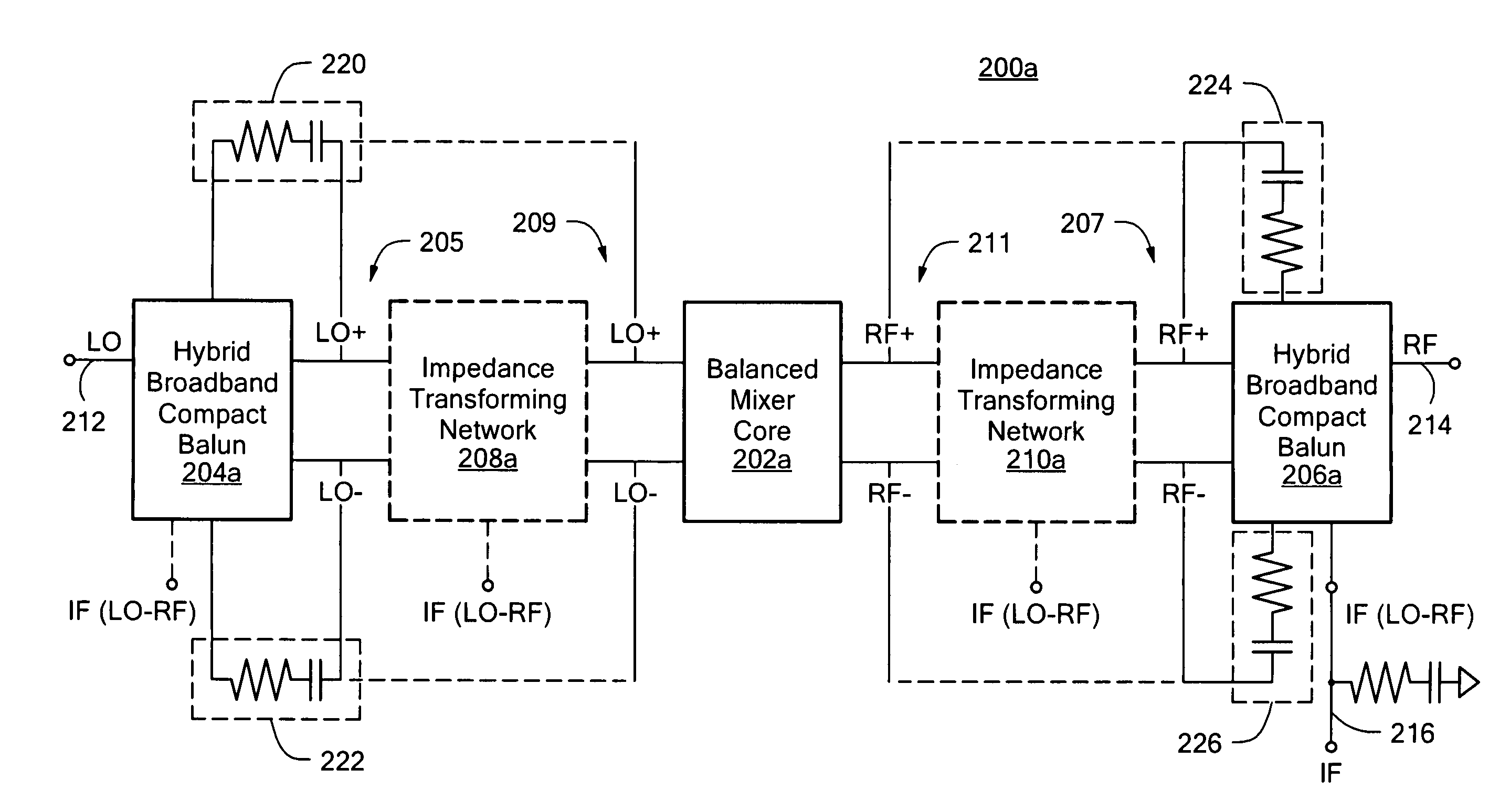
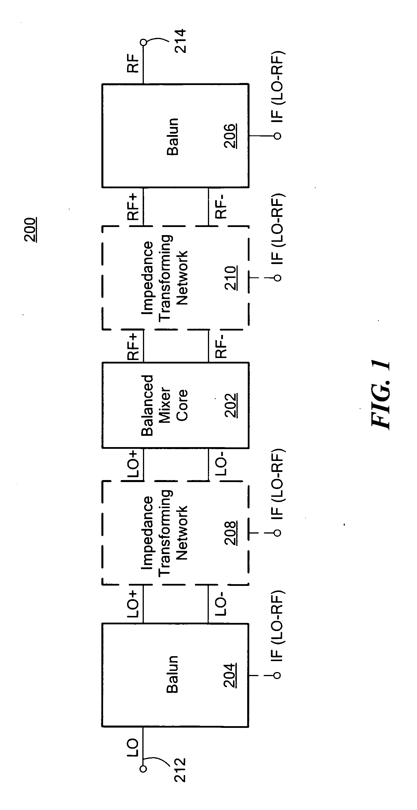
[0031]A conventional double balance mixer 200, FIG. 1, includes a balanced mixer core 202 being supplied by two baluns 204, 206 which may include various types of baluns, such as a Marchand, back / wave or hybrid balun. There optionally may also be impedance transforming networks 208, 210 as conventionally used. The balanced ...


PUM


Abstract

An improved double balanced mixer is provided which in one embodiment includes a first balun for receiving a first single input and providing a first balanced output having two ports, a second balun for receiving a second single input and providing a second balanced output having two ports, and a balanced mixer core responsive to the first and second balanced outputs to provide a mixed signal from the first and second single inputs. The first balun includes an RC network coupled between at least one of the ports of the first balanced output and one of ground and a common mode node of the first balun to improve the linearity of the double balanced mixer.

Description

RELATED APPLICATIONS[0001]This application hereby claims the benefit of and priority to U.S. Provisional Application Ser. No. 61 / 398,149, filed on Jun. 22, 2010 under 35 U.S.C. §§119, 120, 363, 365, and 37 C.F.R. §1.55 and §1.78, which application is incorporated herein by reference.FIELD OF THE INVENTION[0002]This invention relates to a double balanced mixer.BACKGROUND OF THE INVENTION[0003]In communication and other electric systems, a signal at one radio frequency (RF) band often needs to be converted to another intermediate frequency (IF) band or vice verse using circuits called frequency converters or mixers. During this signal frequency conversion process at a mixer, the ratio between output signal power level after the conversion and input signal power level before the conversion is called conversion gain (CG), which measures the efficiency of the conversion process. The operating bandwidth of a mixer is often defined as the frequency bands where conversion gain is maintained...

Claims


Application Information

Patent Timeline
Patent Type & Authority Applications(United States)
IPC IPC(8): H04B1/26
CPCH03D7/1408H03D7/1441H03D2200/0023H03H7/42H03D2200/0013H03D7/1458
Inventor JIANG, XINKOECHLIN, MICHAEL
Owner HITTITE MICROWAVE LLC
Why Eureka
Try Eureka